Isuzu Rodeo UE. Manual — part 116
5C–25
POWER–ASSISTED BRAKE SYSTEM
Vacuum Booster Assembly
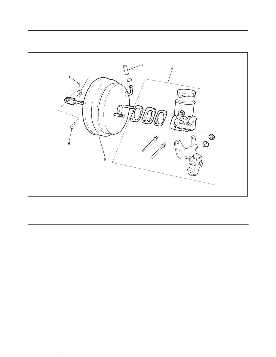
Vacuum Booster Assembly and Associated Parts
331RW005
Legend
(1) Pin
(2) Vacuum Booster Fixing Nut
(3) Vacuum Hose
(4) Master Cylinder
(5) Vacuum Booster
(6) Snap Pin
Removal
1. Before removing the vacuum booster assembly,
disconnect and remove the brake pipes.
2. Remove master cylinder, refer to “Master Cylinder
Removal” in this section.
CAUTION: When removing the master cylinder from
the vacuum booster, be sure to get rid of the internal
negative pressure of the vacuum booster (by, for
instance, disconnecting the vacuum hose) in
advance.
If any negative pressure remains in the vacuum
booster, the piston may possibly come out when the
master cylinder is being removed, letting the brake
fluid run out.
While removing the master cylinder, further, do not
hold the piston as it can be easily pulled out.
Outside surface of the piston is the surface on which
seals are to slide. Care should be taken to keep the
surface free of cuts and dents.
3. Remove vacuum hose.
4. Disconnect the yoke clevis from the brake pedal.
5. Remove vacuum booster fixing nut.
6. Remove vacuum booster.
Inspection and Repair
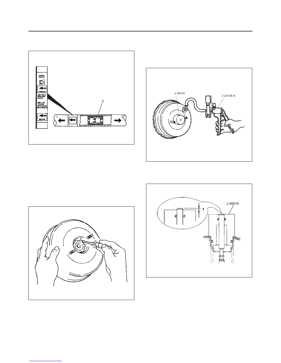
Vacuum Hose
1. Inspect the check valve (2), which is installed inside
the vacuum hose.
2. Air should pass freely from the vacuum booster (3) to
the engine (1).
5C–26 POWER–ASSISTED BRAKE SYSTEM
3. Air should not pass from the engine (1) to the vacuum
booster (3). If it does, the check valve is inoperative
and must be replaced.
360RW001
Installation
1. Perform vacuum booster and vacuum booster push
rod adjustment.
NOTE: When replacing either the master cylinder or
vacuum booster, be sure to measure push rod, and adjust
if required.
2. Remove retainer from vacuum booster front shell
using a small screwdriver. Then gently draw plate and
seal assembly out of the shell inside.
331RS003
3. Set push rod gauge J–39216 on vacuum booster, and
apply negative pressure by means of vacuum pump
J–23738–A so that the pressure in the vacuum
booster becomes 500 mm Hg.
NOTE: Be sure to apply NEGATIVE pressure after
installing a push rod gauge on the vacuum booster.
331RS004
4. Measure dimension (4).
Dimension (4) (Standard): –0.1–0.1 mm
(–0.0039–0.0039 in)
331RW002
5C–27
POWER–ASSISTED BRAKE SYSTEM
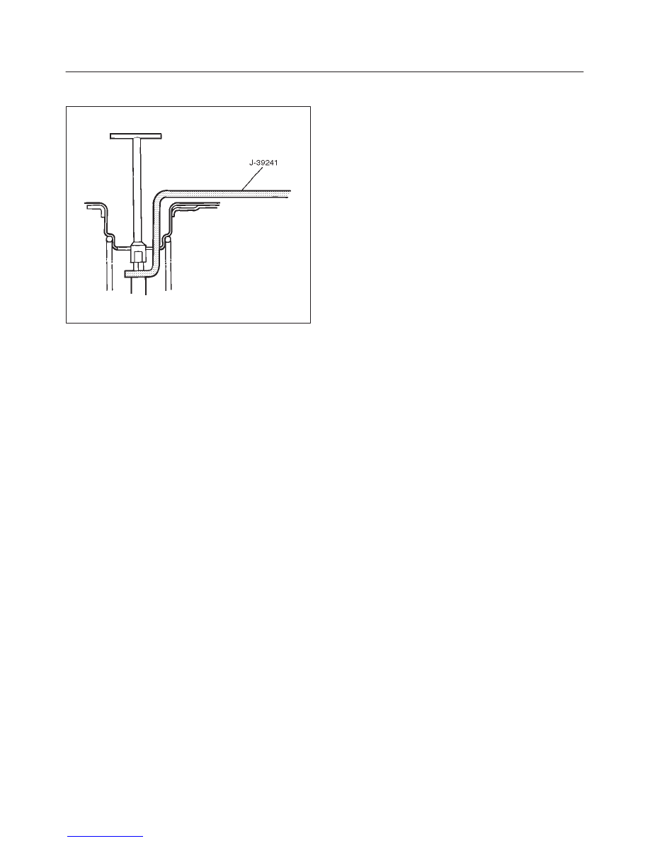
5. If dimension (4) is out of the standard range, adjust
push rod using the Push Rod Support J–39241.
331RW003
6. Mount plate and seal assembly in vacuum booster
front shell. Then install the retainer.
7. Install vacuum booster fixing nut and tighten the
specified torque.
Torque: 15 N·m (11 lb ft)
8. Install yoke clevis.
9. Connect vacuum hose and make sure that the arrow
on the hose points in the direction of the engine.
10. Install master cylinder, refer to “Master Cylinder
Installation” in this section.
5C–28 POWER–ASSISTED BRAKE SYSTEM
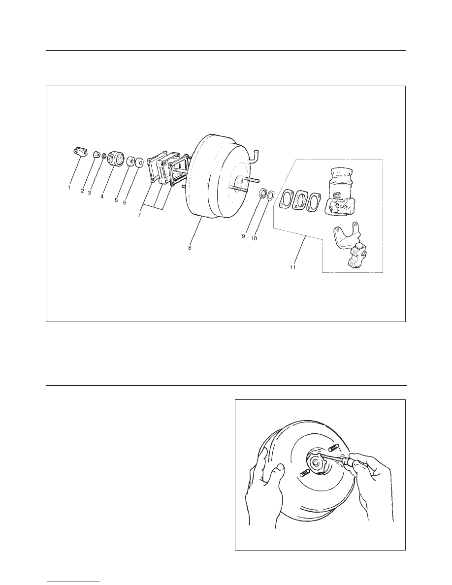
Exterior Components
Exterior Components and Associated Parts
331RW006
Legend
(1) Yoke Clevis
(2) Lock Nut
(3) Retaining Clip
(4) Valve Body Guard
(5) Silencer
(6) Filter
(7) 2 Gaskets and Spacer
(8) Vacuum Booster
(9) Retainer
(10) Plate and Seal Assembly
(11) Master Cylinder
Removal
1. Remove master cylinder. Refer to “Master Cylinder”
in this section.
2. Remove vacuum booster. Refer to “Vacuum Booster”
in this section.
3. Remove yoke clevis.
4. Remove lock nut.
5. Remove retaining clip.
6. Remove valve body guard.
7. Remove silencer.
8. Remove filter.
9. Remove 2 gaskets and spacer.
10. Remove retainer, using a small screwdriver to pry out
the retainer. Gently pull out the plate and seal
assembly from the shell.
331RS003
Нет комментариевНе стесняйтесь поделиться с нами вашим ценным мнением.
Текст