Isuzu Rodeo UE. Manual — part 119
5C–37
POWER–ASSISTED BRAKE SYSTEM
Removal
1. Raise the vehicle and support with suitable safety
stands.
2. Concernig wheel and tire assembly, refer to “Wheels
and Tires System” in Section 3E.
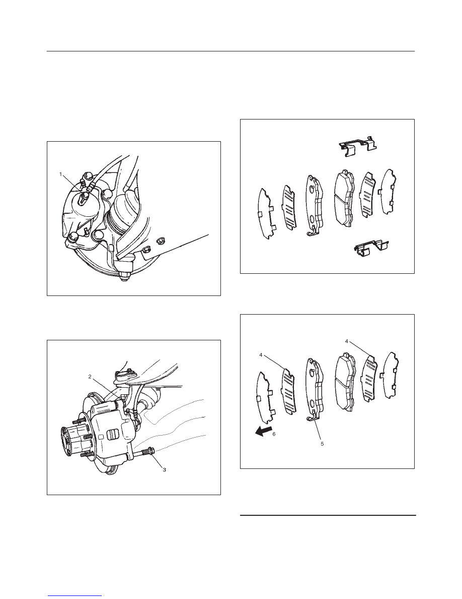
3. Remove the bolt and gaskets, then disconnect the
flexible hose from the caliper and after disconnecting
the flexible hose (1), cap or tape the openings to
prevent entry of foreign material.
302RW009
4. Since the brake fluid flows out from the connecting
coupler, place a drain pan under the vehicle.
5. Remove guide bolt (2).
6. Remove lock bolt (3).
302RW010
7. Remove caliper assembly.
8. Remove support bracket with pad assembly and take
care not to damage the flexible brake hose when
removing the support bracket.
9. Remove pad assembly with shim and mark the lining
locations if they are to be reinstalled.
10. Remove clip.
Installation
1. Install clip.
302RS005
2. Apply special grease (approximately 0.2 g) to both
contacting surfaces of the inner shims (4). Wipe off
extruded grease after installing. Install pad assembly
with shim.
302RW011
Legend
(4) Inner Shim
(5) Wear Indicator
(6) Inner Side
5C–38 POWER–ASSISTED BRAKE SYSTEM
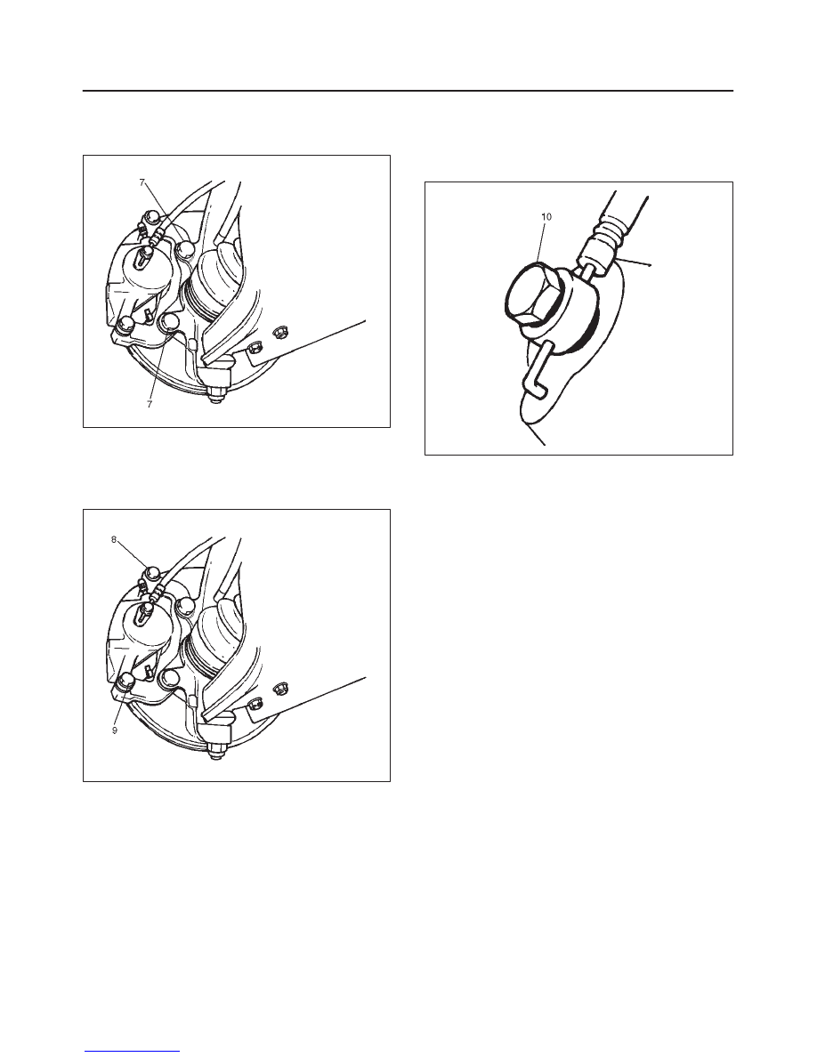
3. Install support bracket and tighten the bolt (7) to the
specified torque.
Torque: 155 N·m (115 lb ft)
302RW012
4. Install caliper assembly.
5. Install lock bolt (9) and guide bolt (8) and tighten the
bolt to the specified torque.
Torque: 74 N·m (54 lb ft)
302RW013
6. Install brake flexible hose, always use new gaskets
and be sure to put the hooked edge of the flexible
hose end into the anti–rotation cavity then tighten the
I–bolt (10) to the specified torque.
Torque: 35 N·m (26 lb ft)
302RW014
7. Install wheel and tire assembly, referring to “Wheels
and Tires System” in Section 3E.
8. Bleed brakes. Refer to “Hydraulic Brakes” in this
section.
5C–39
POWER–ASSISTED BRAKE SYSTEM
Front Disc Brake Caliper
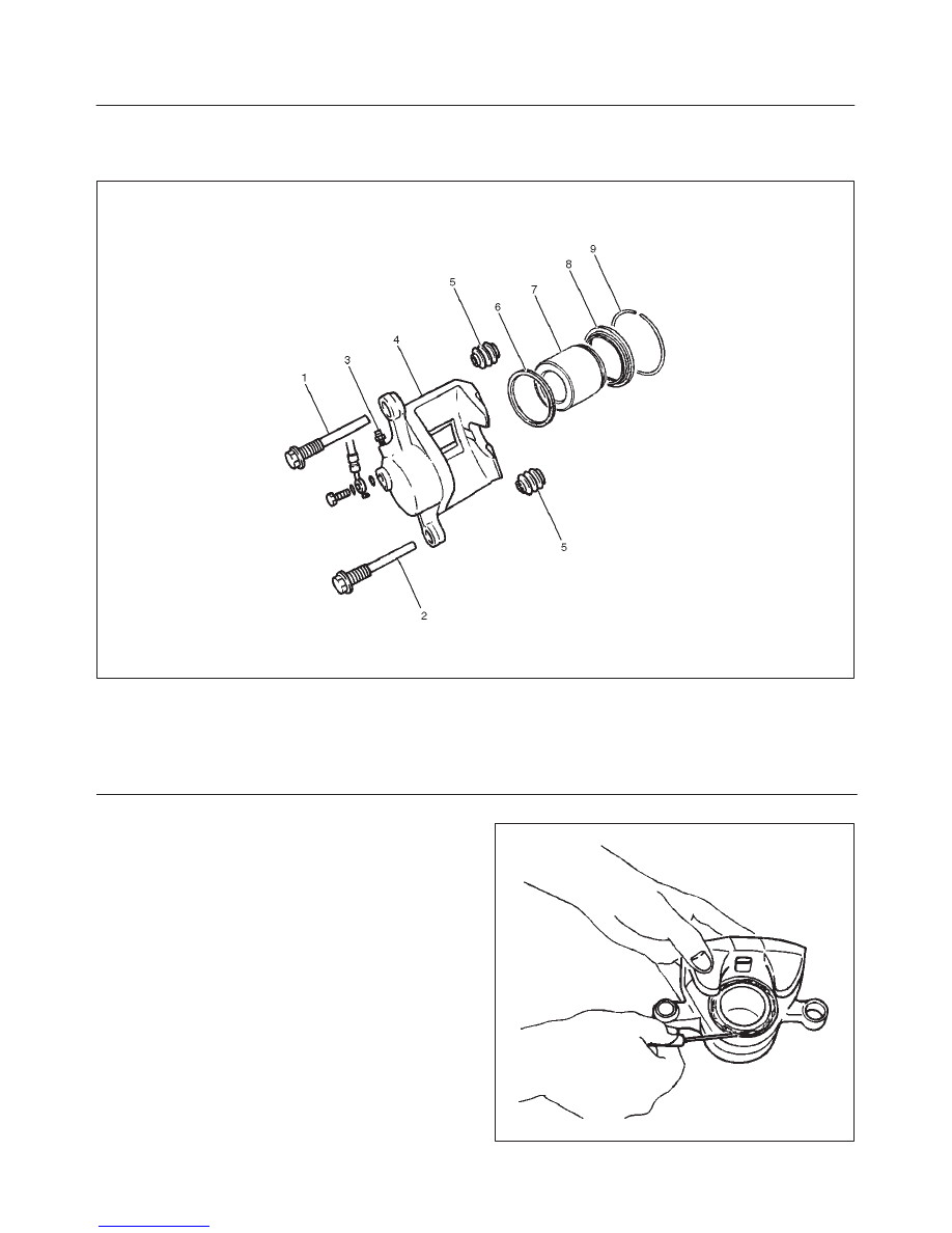
Front Disc Brake Caliper Disassembled View
302RW015
Legend
(1) Guide Bolt
(2) Lock Bolt
(3) Bleeder with Cap
(4) Caliper Body
(5) Dust Boot: Guide Bolt and Lock Bolt
(6) Piston Seal
(7) Piston
(8) Dust Boot: Piston
(9) Dust Boot Ring
Disassembly
1. Remove guide bolt.
2. Remove lock bolt.
3. Remove dust boot: guide bolt and lock bolt.
4. Remove dust boot ring, using a small screwdriver.
302RS016
5C–40 POWER–ASSISTED BRAKE SYSTEM
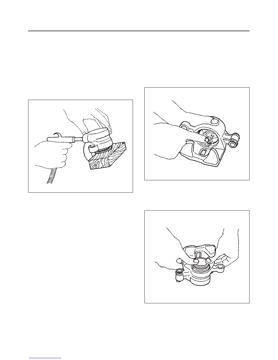
5. Insert a block of wood into the caliper and force out
the piston by blowing compressed air into the caliper
at the flexible hose attachment. This procedure must
be done prior to removal of the dust boot.
Remove piston.
WARNING: DO NOT PLACE YOUR FINGERS IN
FRONT OF THE PISTON IN AN ATTEMPT TO CATCH
OR PROTECT IT WHEN APPLYING COMPRESSED
AIR. THIS COULD RESULT IN PERSONAL INJURY.
CAUTION: Use just enough air to ease the piston
out of the bore. If the piston is blown out, it may be
damaged.
302RS017
6. Remove dust boot: piston.
7. Remove piston seal.
8. Remove bleeder with cap.
9. Remove caliper body.
Inspection and Repair
Make necessary parts replacement, if wear, damage,
corrosion or any other abnormal conditions are found
through inspection.
Check the following parts:
f
Rotor
f
Cylinder body
f
Cylinder bore
f
Piston
f
Guide bolt, lock bolt
f
Support bracket
NOTE: The piston seal, boot ring and dust boot are to be
replaced each time the caliper is overhauled. Discard
these used rubber parts and replace them with new ones.
Reassembly
1. Install caliper body.
2. Install bleeder with cap and tighten the cap to the
specified torque.
Torque: 8 N·m (69 lb in)
3. Apply special rubber grease to the piston seal and
cylinder wall, then insert the piston seal into the
cylinder. The special rubber grease is included in the
repair kit.
302RS018
4. When inserting the piston into the cylinder, use finger
pressure only and do not use a mallet or other impact
tool, since damage to the cylinder wall or piston seal
can result.
Install piston.
302RS019
Нет комментариевНе стесняйтесь поделиться с нами вашим ценным мнением.
Текст