Isuzu Rodeo UE. Manual — part 118
5C–33
POWER–ASSISTED BRAKE SYSTEM
Removal
NOTE: If a squealing noise occurs from the front brake
while driving, check the pad wear indicator plate. If the
indicator plate contacts the rotor, the disc pad assembly
should be replaced.
f
Draw out two–thirds of the brake fluid from the
reservoir.
f
Raise the vehicle and support it with suitable safety
stands.
1. Remove wheel and tire assembly, refer to “Wheels
and Tires System” in Section 3E.
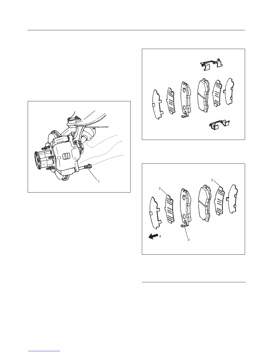
2. Remove lock bolt (1).
302RW004
3. Rotate caliper assembly and support the caliper
assembly so that the brake hose is not stretched or
damaged.
4. Remove pad assembly with shim.
5. Remove Clip.
Installation
1. Install clip.
302RS005
2. Apply special grease (approximately 0.2 g) to both
contacting surfaces of the inner shims (2). Wipe off
extruded grease after installing. Install pad assembly
with shim.
302RW005
Legend
(2) Inner Shim
(3) Wear Indicator
(4) Inner Side
5C–34 POWER–ASSISTED BRAKE SYSTEM
302RW006
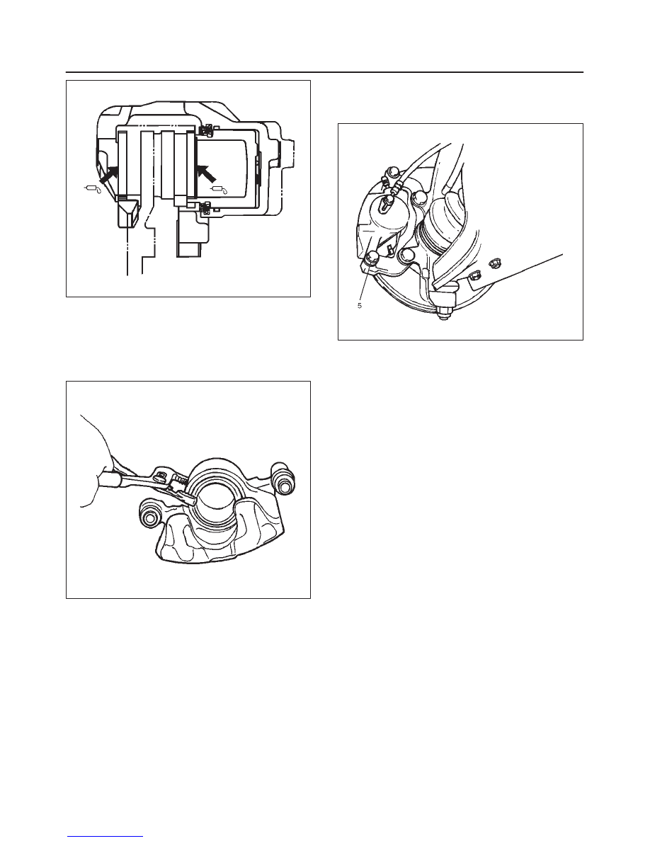
3. Use adjustable pliers to bottom the piston into the
caliper bore. Be careful do not damage the piston
boot and do not damage the flexible hose by twisting
or pulling it.
Install caliper assembly.
Set caliper assembly in place.
302RS008
4. Install lock bolt (5) and tighten the bolt to the specified
torque.
Torque: 74 N·m (54 lb ft)
302RW018
5. Install wheel and tire assembly, refer to “Wheels and
Tires System” in Section 3E.
6. Pump the brake pedal several times to make sure that
the pedal is firm. Check the brake fluid level in the
reservoir after pumping the brakes.
5C–35
POWER–ASSISTED BRAKE SYSTEM
Front Disc Brake Rotor
Inspection
In the manufacturing of the brake rotor, all the tolerances
regarding surface finish, parallelism and lateral runout are
held very closely. Maintaining these tolerances provides
the surface necessary to assure smooth brake operation.
Lateral Runout
Lateral runout is the movement of the rotor from side to
side as it rotates on the spindle. This could also be
referred to as “rotor wobble”.
This movement causes the piston to be knocked back into
its bore. This results in additional pedal travel and a
vibration during braking.
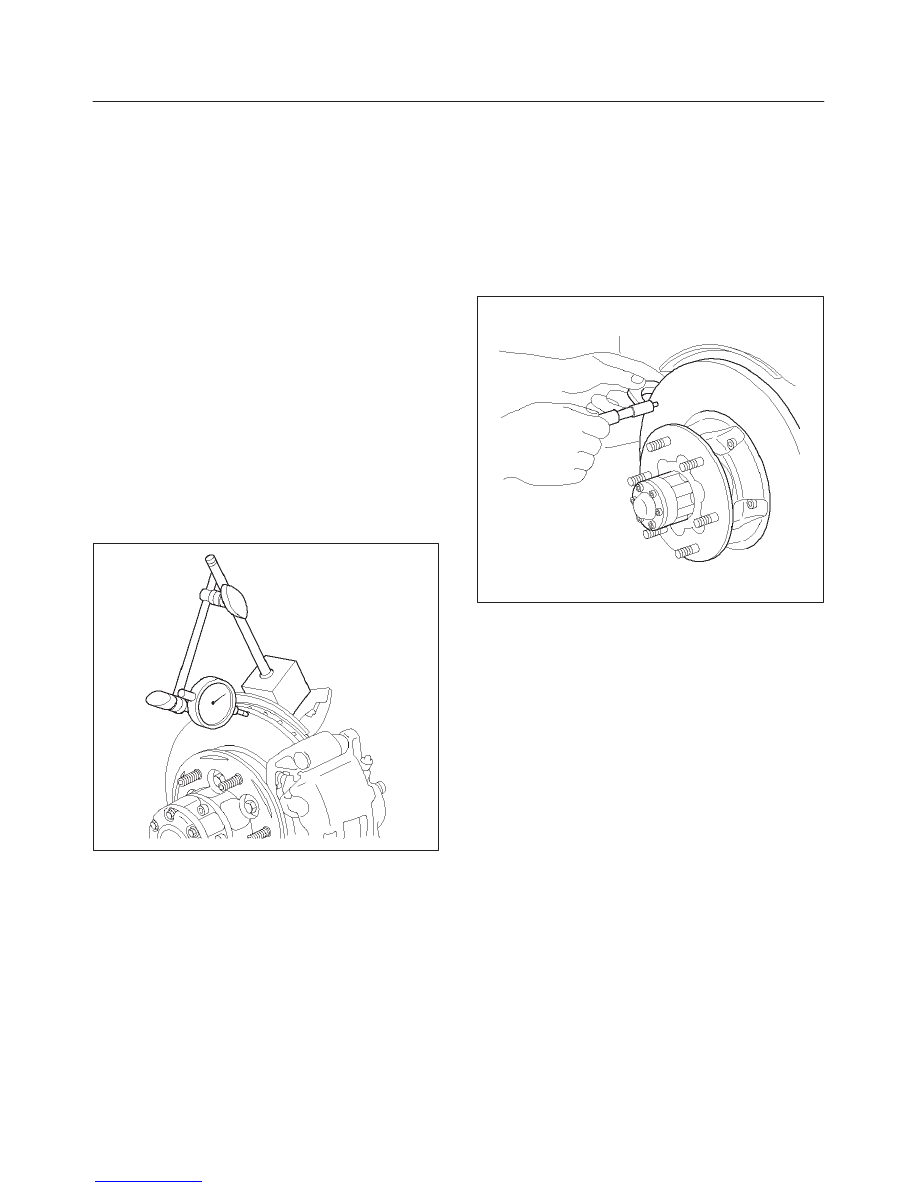
Checking Lateral Runout
1. Adjust the wheel bearing correctly, refer to
“Differential” in Section 4A.
2. Attach a dial indicator to some portion of the
suspension so that the stem contacts the rotor face
about 29 mm (1.14 in) from the rotor edge.
3. Move the rotor one complete rotation and the lateral
runout should not exceed 0.13 mm (0.005 in).
Maximum runout: 0.13 mm (0.005 in)
411RS019
Parallelism
Parallelism is the measurement of thickness of the rotor
at four or more points around the circumference of the
rotor. All measurement must be made at 29 mm (1.14 in)
from the edge of the rotor.
The rotor thickness must not vary more than 0.010 mm
(0.0004 in) from point to point.
Maximum runout: 0.010 mm (0.0004 in)
411RS018
Replacing Brake Rotors
When installing new brake rotors, do not refinish the
surfaces. These parts are at the correct level of surface
finish.
Refinishing Brake Rotors
Accurate control of the rotor tolerances is necessary for
proper performance of the disc brakes. Machining of the
rotor should be done only with precision equipment. All
brake rotors have a minimum thickness dimension cast
into them. This dimension is the minimum wear
dimension and not a refinish dimension. The minimum
wear dimension is 24.60 mm (0.969 in). The minimum
refinish dimension is 24.97 mm (0.983 in).
When refinishing rotors, always use sharp cutting tools or
bits. Dull or worn tools leave a poor surface finish which
will affect initial braking performance. Vibration
dampening attachments should always be used when
refinishing braking surfaces. These attachments
eliminate tool chatter and will result in better surface
finish.
After refinishing, replace any rotor that does not meet the
minimum thickness of 24.97 mm (0.983 in). Do not use a
brake rotor that will not meet the specification.
Minimum wear dimension: 24.60 mm (0.969 in)
Refinish dimension: 24.97 mm (0.983 in)
5C–36 POWER–ASSISTED BRAKE SYSTEM
411RW003
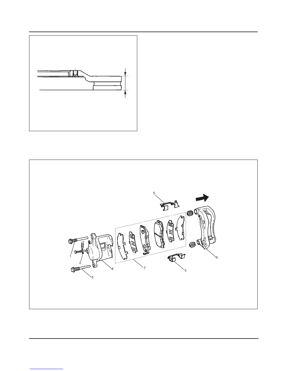
Front Disc Brake Caliper Assembly
Front Disc Brake Caliper Assembly and Associated Parts
302RW008
Legend
(1) Guide Bolt
(2) Brake Flexible Hose
(3) Lock Bolt
(4) Caliper Assembly
(5) Clip
(6) Support Bracket with Pad Assembly
(7) Pad Assembly
Нет комментариевНе стесняйтесь поделиться с нами вашим ценным мнением.
Текст