Isuzu Rodeo UE. Manual — part 141
6A–53
ENGINE MECHANICAL (X22SE 2.2L)
Piston and Connecting Rod
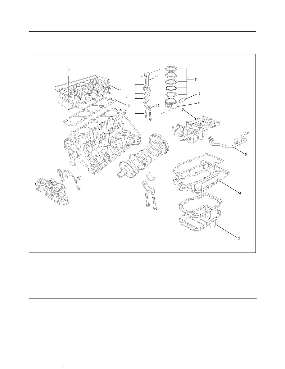
Piston, Connecting Rod and Associate Parts
015RW037
Legend
(1) Cylinder Head Assembly
(2) Cylinder Head Gasket
(3) Oil Pan Assembly
(4) Pan Support
(5) Oil Strainer
(6) Balance Unit Assembly
(7) Piston and Connecting Rod Assembly
(8) Piston Ring
(9) Piston Pin
(10) Piston
(11) Connecting Rod
(12) Connecting Rod Cap
Disassembly
1. Remove cylinder head assembly (1), refer to
“Cylinder Head Removal” in this manual.
2. Remove cylinder head gasket (2).
3. Remove oil pan assembly and oil pan support (3)
refer to“Oil Pan and Oil Pan Support” in this manual.
4. Remove oil strainer.
5. Remove balance unit assembly.
6. Remove connecting rod cap with connecting rod
lower.
6A–54
ENGINE MECHANICAL (X22SE 2.2L)
7. Remove piston and connecting rod assembly (7).
NOTE: Before removing piston and connecting rod
assembly, measure thrust clearance.
f
Remove any ridge or carbon build up from the top
end of the cylinder.
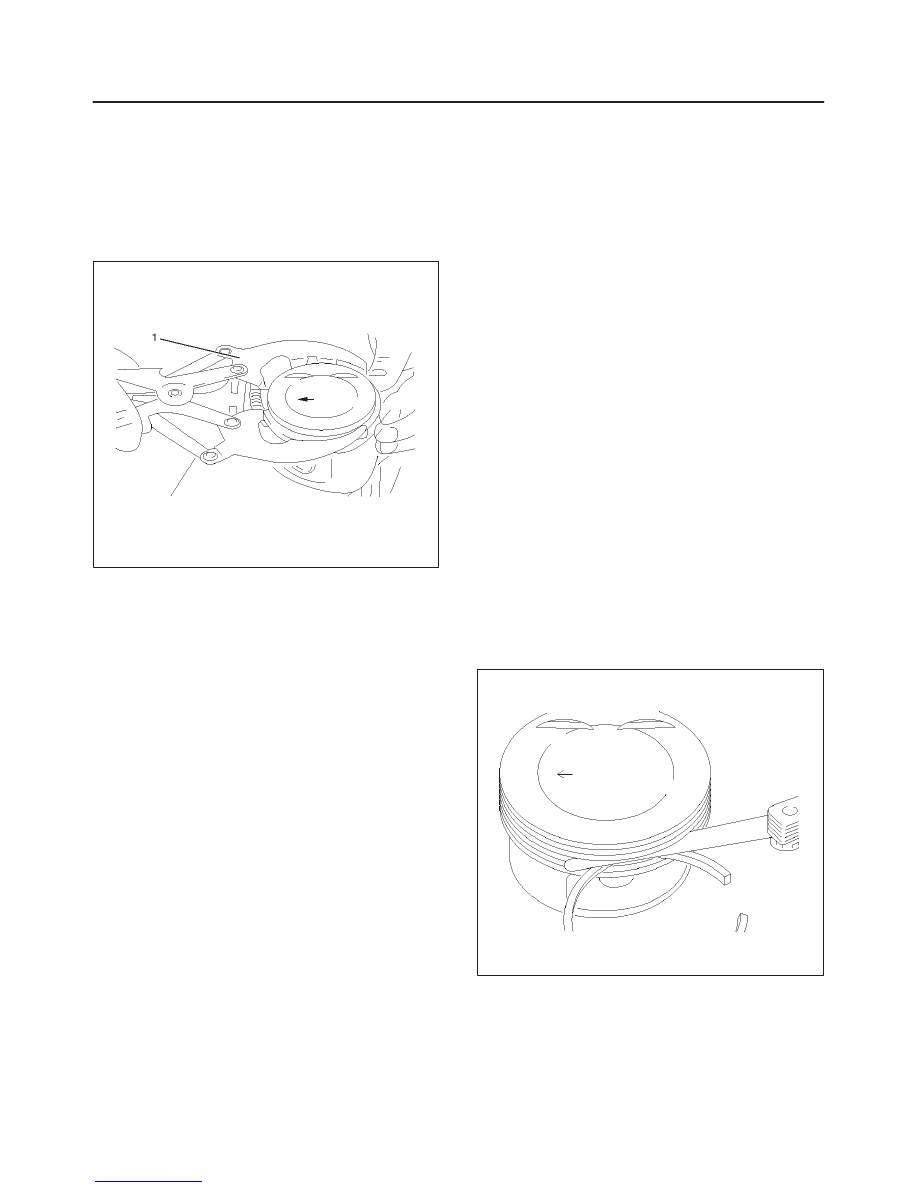
8. Remove the piston rings (8) with a piston ring
expander. Arrange the removed piston rings in the
cylinder number order.
015RW024
9. Remove the piston pin (9).
f
Heat the connecting rod and the piston pin with oil
heater, when it temperature is keep at
280
°
C–320
°
C.
f
Push the piston pin with brass bar.
NOTE: Keep the parts removed from each cylinder
separate. All parts must be reinstalled in their original
positions.
10. Piston (10).
11. Connecting rod (11).
Inspection and Repair
Pistons (10)
Carefully clean away all the carbon adhering to the piston
head and the piston ring grooves.
NOTE: Never use a wire brush to clean the pistons.
Damage will result. Visually check each piston for
cracking, scoring, and other signs of excessive wear. If
any of the above conditions are found, the piston must be
replaced.
Piston Rings (8)
Any worn or damaged part discovered during engine
overhaul must be replaced with a new one.
1. Ring end gap measurement
f
Insert the piston ring into the bore.
f
Push the ring by the piston, at a right angle to the
wall, into the point at which the cylinder bore
diameter is the smallest.
f
Measure the ring end gap.
Compression Ring
1st ring
Standard:
0.30 mm–0.50 mm
(0.0118 in–0.0195 in)
2nd ring
Standard:
0.30 mm–0.50 mm
(0.0118 in–0.0195 in)
Oil ring
Standard:
0.40 mm–1.40 mm
(0.0156 in–0.0546 in)
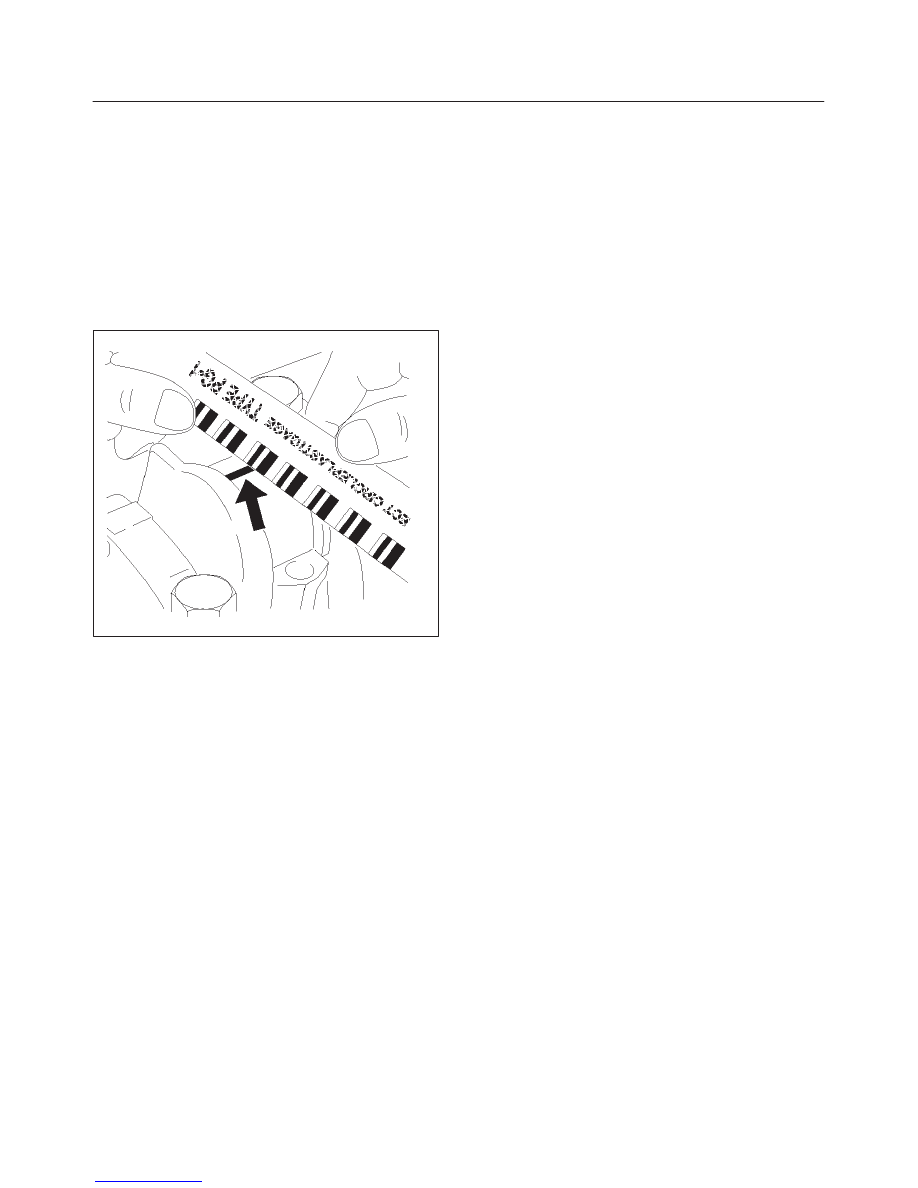
2. Measure the clearance between the piston ring
groove and the piston ring with a feeler gauge. If the
piston ring groove / piston ring clearance exceeds the
specified limit, the piston must be replaced.
Compression Ring Clearance
Standard : 0.02 mm–0.04 mm
(0.0008 in.–0.0016 in)
015RW025
6A–55
ENGINE MECHANICAL (X22SE 2.2L)
Piston Pin (9)
NOTE: Do not reuse the old piston pin.
1. Use a micrometer to measure the new piston pin
outside diameter in both directions at three different
positions.
2. Measure the inside diameter of the connecting rod
small end. If the fitting interference between the small
end and pin does not conform to the specified value,
the connecting rod must be replaced.
Standard : 0.02 mm–0.041 mm
(0.0008 in–0.0016 in)
014RW077
3. Insert the new pin into the piston and rotate it. If the
pin rotates smoothly with no backlash, the clearance
is normal. If there is backlash or roughness, measure
the clearance. If the clearance exceeds the specified
limit, the piston must be replaced.
Clearance
Standard : 0.011 mm–0.014 mm
(0.0004 in.–0.0005 in)
Connecting Rods (11)
1. Measure the oil clearance between the connecting
rod and the crankshaft.
1. Remove the connecting rod cap nuts and the rod
caps (12).
Arrange the removed rod caps in the cylinder
number order.
2. Clean the rod bearings and the crankshaft pins.
3. Carefully check the rod bearings. If even one
bearing is found to be damaged or badly worn, the
entire bearing assembly must be replaced as a
set. Reinstall the bearings in their original
positions. Apply plastigage to the crank pin.
4. Reinstall the rod caps (12) to their original
positions.
Tighten the rod cap nuts.
1st step: 35 N·m (26 lb ft)
2nd step: 45
°
3rd step: 15
°
NOTE: Do not allow the crankshaft to rotate.
5. Remove the rod caps.
6. Measure the width of the plastigage and
determine the oil clearance. If the oil clearance
exceeds the limit, replace the rod bearing as a
set.
Standard : 0.006 mm–0.031 mm
(0.0002 in–0.0012 in)
Limit : 0.12 mm (0.0047 in)
7. Clean the plastigage from the bearings and the
crankshaft pins.
6A–56
ENGINE MECHANICAL (X22SE 2.2L)
Crankshaft grinding dimensions
mm (in)
(continued)
Production and Service
Con–rod bearing journal dia.
Standard size
(no color code)
48.970 to 48.988 (1.9098–1.9105)
Undersize 0.25 (0.0097)
blue
48.720 to 48.738 (1.9001–1.9008)
Undersize 0.5 (0.0195)
white
48.470 to 48.488 (1.8903–1.891)
Con–rod bearing journal width
Standard size
(no color code)
26.460 to 26.580 (1.0319–1.036)
Undersize 0.25 (0.0097)
blue
26.460 to 26.580 (1.0319–1.036)
Undersize 0.5 (0.0195)
white
26.460 to 26.580 (1.0319–1.036)
Con–rod width
26.338 to 26.390 (1.0271–1.0292)
Reassembly
1. Install connecting rod
2. Install piston
3. Install piston pin
f
Apply a thin coat of engine oil to the piston pin. Try to
insert the piston pin into the piston pin hole with
normal finger pressure.
NOTE: When changing piston / connecting rod
combinations, do not change the piston / piston pin
combination and do not reuse the old piston pin.
f
Attach the piston to the connecting rod with the
piston front mark and the connecting rod front mark
on the same side.
f
Heat the connecting rod small end to a suitable
temperature to ensure smooth installation.
4. Install piston ring with the piston ring expander.
f
New piston rings with “Top” uppermost — use
commercially available pliers.
f
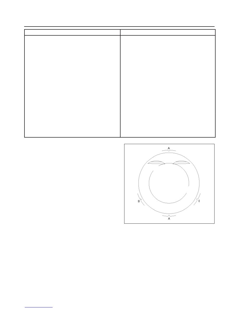
Position ring gaps:
1 — Compression rings 180
°
to each other as
illustrated.
2 — Offset oil control rings 25 to 50 mm/1 to 2 in.
from gap of second compression ring.
015RW026
f
After installation, apply engine oil to the entire
circumference of the piston rings. Check to see that
all the rings rotate smoothly.
5. Install piston and connecting rod assembly.
f
Insert the bearings into the connecting rods and
caps. Apply new engine oil to the bearing faces and
nuts.
f
Tighten the connecting rod cap nuts in 3 steps:
1st step : 35 N·m (26 lb ft)
2nd step: 45
°
3rd step: 15
°
Нет комментариевНе стесняйтесь поделиться с нами вашим ценным мнением.
Текст