Isuzu Rodeo UE. Manual — part 139
6A–45
ENGINE MECHANICAL (X22SE 2.2L)
Camshaft
Camshaft and Associated Parts
011RW023
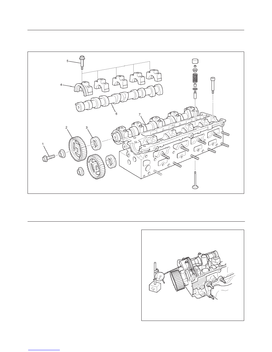
Legend
(1) Camshaft Pulley Fixing Bolt
(2) Camshaft Pulley
(3) Oil Seal
(4) Camshaft Bracket
(5) Camshaft Bracket Fixing Bolt
(6) Camshaft Assembly Exhaust
(7) Camshaft Assembly Intake
Disassembly
1. Remove fixing bolt (1) for camshaft pulley (2).
2. Remove oil seal (3).
014RW035
6A–46
ENGINE MECHANICAL (X22SE 2.2L)
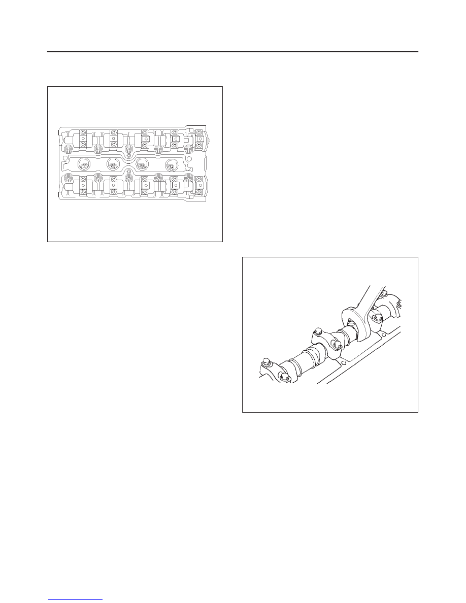
3. Remove oil seal (3).
4. Remove twenty fixing bolts (5) from inlet and exhaust
camshaft bracket, then camshaft brackets (4).
011RW015
5. Remove camshaft assembly (6), (7).
Reassembly
1. Install camshaft drive gear assembly and tighten
three bolts to specified torque.
Torque: 50 N·m (37 lb ft) + 60
°
+ 15
°
2. Install camshaft assembly and camshaft brackets,
tighten twenty bolts on one side bank to the specified
torque.
1. Apply engine oil to camshaft journal and bearing
surface of camshaft bracket.
2. Align timing mark on intake camshaft and exhaust
camshaft to timing mark on camshaft drive gear
(one dot).
3. Tighten twenty bolts on numerical order one side
bank shown in the illustration.
Torque: 8 N·m (6 lb ft)
4. If it required to replace oil seal of camshaft drive
gear, use J–42609 for install the oil seal.
5. Tighten bolt for camshaft drive gear assembly
pulley to the specified torque.
Torque: 50 N·m (37 lb ft) + 60
°
+ 15
°
014RW036
6A–47
ENGINE MECHANICAL (X22SE 2.2L)
Crankshaft
Crankshaft and Associated Parts
015RW008
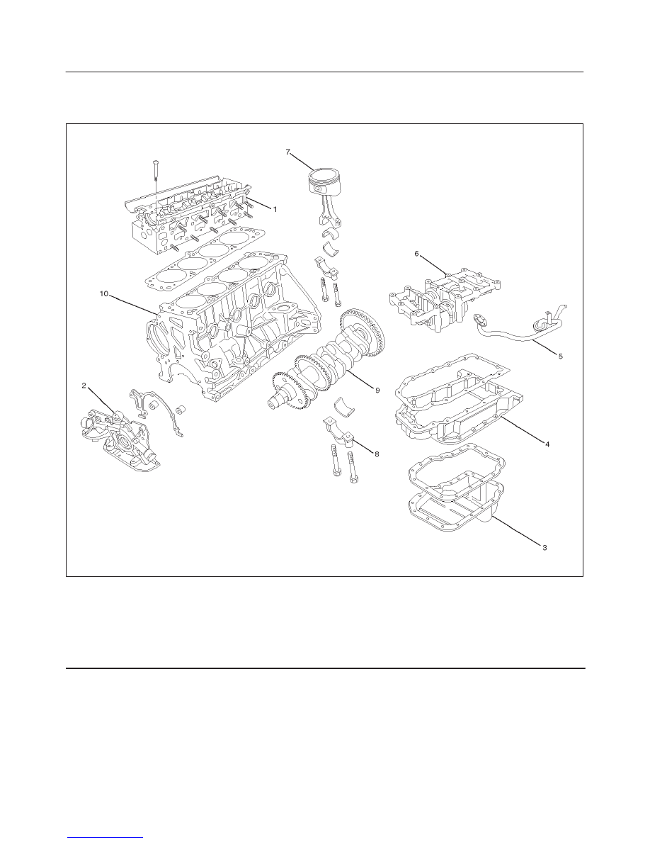
Legend
(1) Cylinder Head Assembly
(2) Oil Pump Assembly
(3) Pan
(4) Pan Support
(5) Oil Strainer
(6) Balance Unit Assembly
(7) Piston and Connecting Rod Assembly
(8) Main Bearing Cap
(9) Crankshaft
(10) Cylinder Block Assembly
Disassembly
1. Remove cylinder head assembly (1). Refer to
“Cylinder head” in this manual.
2. Remove oil pan (3).
CAUTION: Take care not to damage or deform the
sealing flange surface of crankcase.
3. Remove oil pan support (4).
4. Remove oil strainer (5).
5. Remove oil pump assembly (5).
6. Balance unit assembly.
7. Remove piston and connecting rod assembly (7).
Refer to “Piston, Piston Ring and Connecting Rod” in
this manual.
8. Remove flywheel.
9. Remove rear oil seal and oil baffle plate.
6A–48
ENGINE MECHANICAL (X22SE 2.2L)
10. Remove main bearing cap (8).
11. Remove crankshaft (9).
12. Remove crankshaft pulse pickup sensor disc.
Inspection and Repair
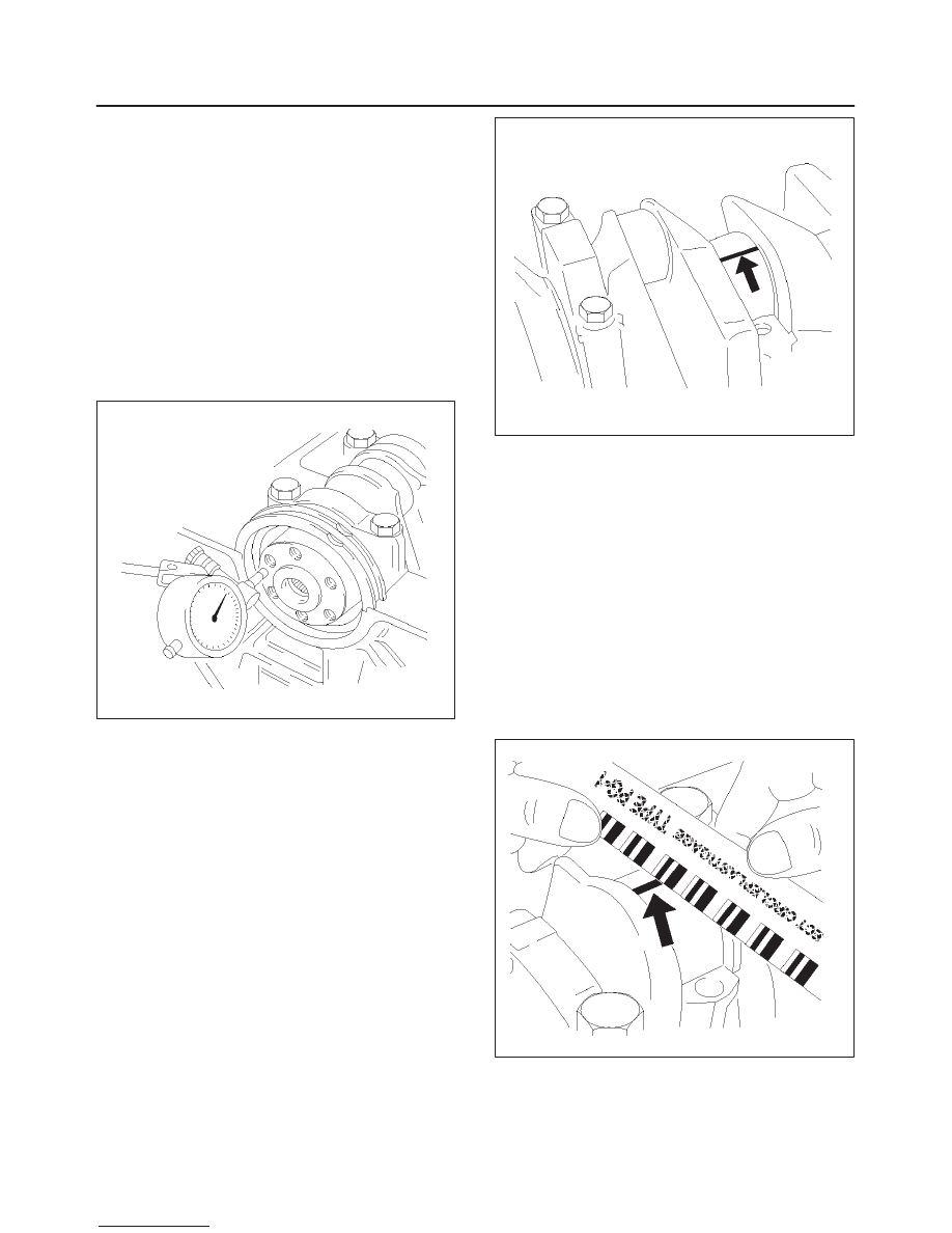
1. Crankshaft
Set the dial indicator as shown in the illustration and
measure the crankshaft thrust clearance. If the thrust
clearance exceeds the specified limit, replace the
thrust bearings as a set.
Thrust Clearance
Standard : 0.01 mm–0.02 mm
(0.0004 in–0.0008 in)
Limit : 0.21 mm (0.0118 in)
014RW079
Main Bearing Clearance
1. Remove the bearing caps and measure the oil
clearance.
2. Remove the main bearing cap fixing bolts.
Arrange the removed main bearing caps in the
cylinder number order.
Remove the main bearings.
3. Remove the crankshaft.
Remove the main bearings.
4. Clean the upper and lower bearings as well as the
crankshaft main journal.
5. Check the bearings for damage or excessive wear.
The bearings must be replaced as a set if damage or
excessive wear is discovered during inspection.
6. Set the upper bearings and the thrust washers to their
original positions.
Carefully install the crankshaft.
7. Set the lower bearings to the bearing cap original
position.
8. Apply plastigage to the crankshaft journal unit as
shown in the illustration.
014RW055
9. Install main bearing caps, and tighten each bolt to the
specified torque.
Main bearing caps bolts.
Torque:
1st step: 50 N·m (37 lb ft)
2nd step: 45
°
3rd step: 15
°
Torque : 39 N·m (29lb ft)
10. Measure the plastigage width and determine the oil
clearance. If the oil clearance exceeds the specified
limit, replace the main bearings as a set and/or
replace the crankshaft.
Standard : 0.015 mm–0.04 mm
(0.0007 in–0.0016 in)
Limit : 0.12 mm (0.0047 in)
014RW077
11. Clean the plastigage from the bearings and the
crankshaft.
Remove the crankshaft and the bearings.
Нет комментариевНе стесняйтесь поделиться с нами вашим ценным мнением.
Текст