Isuzu Rodeo UE. Manual — part 536
8B–12 WIPER/WASHER SYSTEM
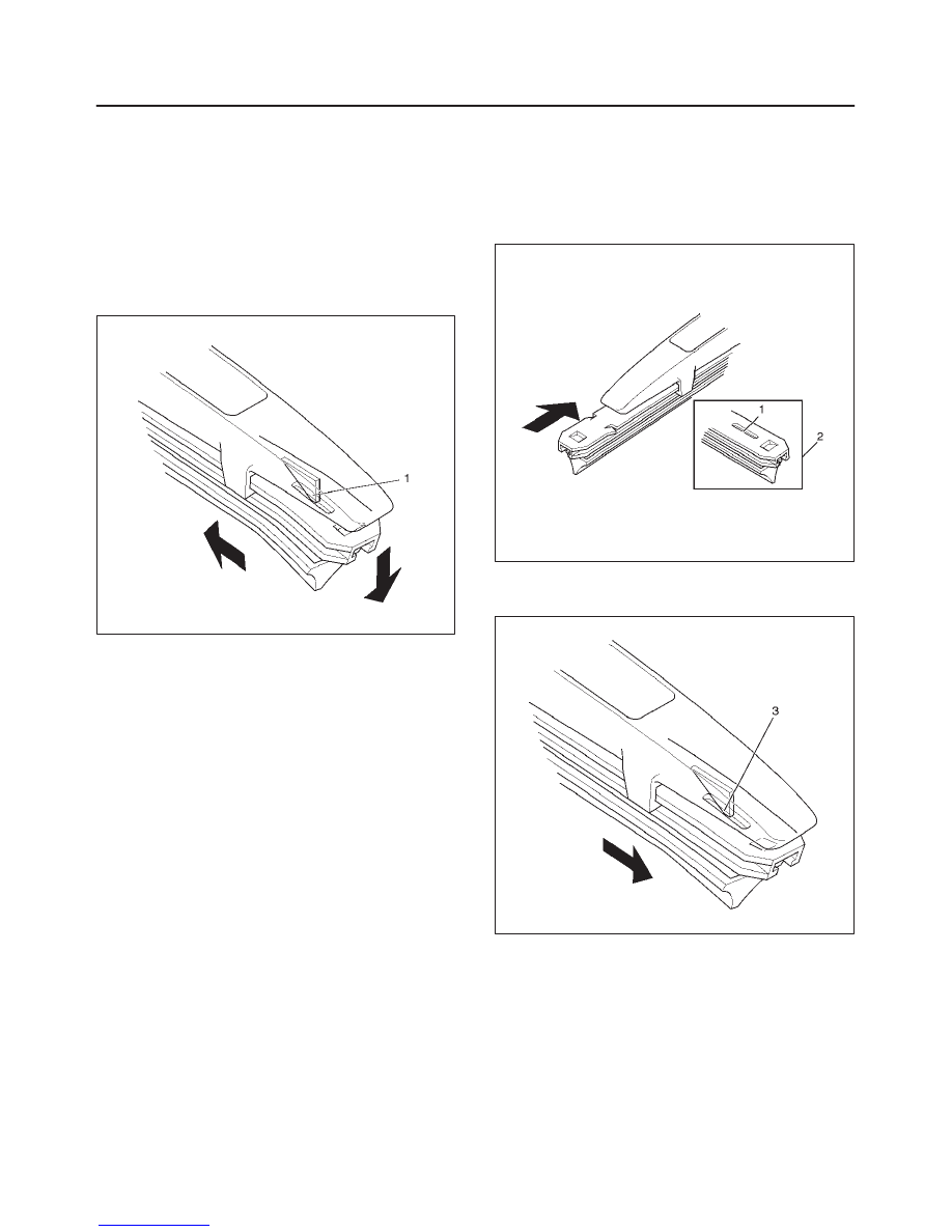
Rear Wiper Blade Rubber
Removal
1. Remove the wiper blade from the wiper arm.
2. Push out the wiper rubber from the wiper blade by
sliding it horizontally while holding down the rubber on
the wiper blade convex (1) side.
CAUTION: When the wiper blade has been
removed, wrap the tip of the wiper arm with cloth, to
avoid damaging the glass.
880RW022
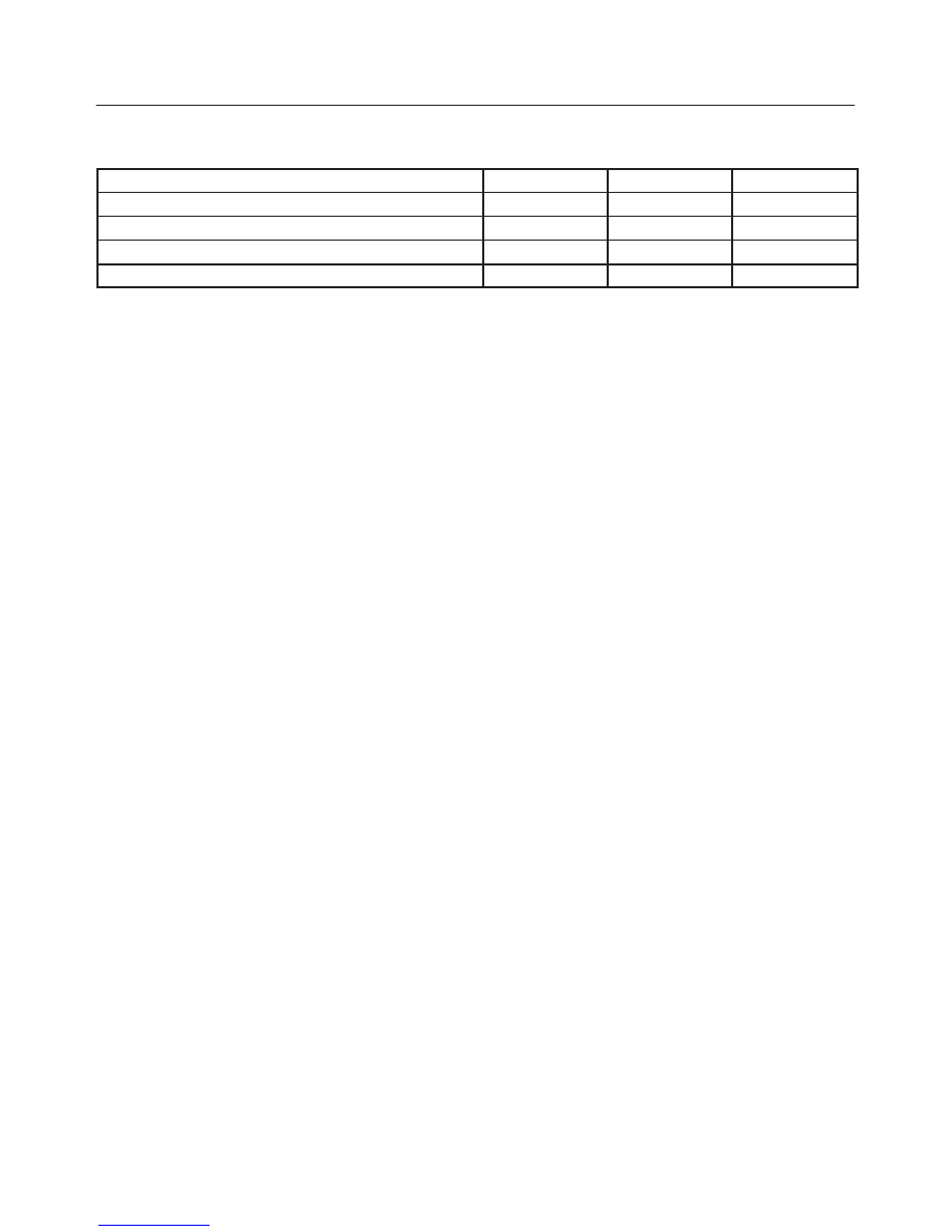
Installation
1. Install the wiper blade rubber.
f
Insert the tip of wiper rubber (2) from the opposite
side of removal in the arrow direction.
880RX001
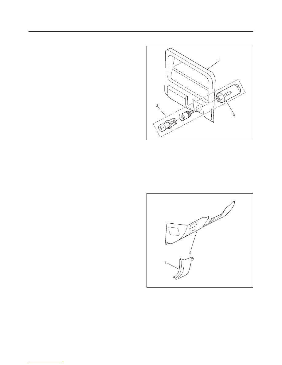
f
Check if the convex part (3) of wiper blade is
installed in the groove of the wiper rubber.
880RX002
WIPER/WASHER SYSTEM
8B–13
Main Data and Specifications
Torque Specifications
Application
N·m
Lb Ft
Lb In
Windshield Wiper Motor Shaft Nut
14
—
122
Windshield Wiper Arm Nuts
23
17
—
Rear Wiper Motor Shaft Nut
10
—
87
Rear Wiper Arm Nut
14
—
122
ENTERTAINMENT
8C–1
RODEO
BODY AND ACCESSORIES
ENTERTAINMENT
CONTENTS
Service Precaution
8C–1
. . . . . . . . . . . . . . . . . . . . . .
Cigarette Lighter
8C–2
. . . . . . . . . . . . . . . . . . . . . . . .
General Description
8C–2
. . . . . . . . . . . . . . . . . . . . .
Removal
8C–2
. . . . . . . . . . . . . . . . . . . . . . . . . . . . .
Installation
8C–2
. . . . . . . . . . . . . . . . . . . . . . . . . . . .
Digital Clock
8C–2
. . . . . . . . . . . . . . . . . . . . . . . . . . . .
Removal
8C–2
. . . . . . . . . . . . . . . . . . . . . . . . . . . . .
Installation
8C–3
. . . . . . . . . . . . . . . . . . . . . . . . . . . .
Rod Type Antenna
8C–3
. . . . . . . . . . . . . . . . . . . . . .
Removal
8C–3
. . . . . . . . . . . . . . . . . . . . . . . . . . . . .
Installation
8C–3
. . . . . . . . . . . . . . . . . . . . . . . . . . . .
Accessory Socket
8C–4
. . . . . . . . . . . . . . . . . . . . . . .
Front Accessory Socket
8C–4
. . . . . . . . . . . . . . . .
Rear Accessory Socket
8C–4
. . . . . . . . . . . . . . . .
Radio
8C–5
. . . . . . . . . . . . . . . . . . . . . . . . . . . . . . . . . .
Removal
8C–5
. . . . . . . . . . . . . . . . . . . . . . . . . . . . .
Installation
8C–5
. . . . . . . . . . . . . . . . . . . . . . . . . . . .
Speaker
8C–6
. . . . . . . . . . . . . . . . . . . . . . . . . . . . . . . .
Front Speaker
8C–6
. . . . . . . . . . . . . . . . . . . . . . . . .
Tweeter Assembly
8C–6
. . . . . . . . . . . . . . . . . . . . .
Rear Speaker
8C–6
. . . . . . . . . . . . . . . . . . . . . . . . .
Horn
8C–7
. . . . . . . . . . . . . . . . . . . . . . . . . . . . . . . . . . .
Removal
8C–7
. . . . . . . . . . . . . . . . . . . . . . . . . . . . .
Installation
8C–7
. . . . . . . . . . . . . . . . . . . . . . . . . . . .
Service Precaution
WARNING: THIS VEHICLE HAS A SUPPLEMENTAL
RESTRAINT SYSTEM (SRS). REFER TO THE SRS
COMPONENT AND WIRING LOCATION VIEW IN
ORDER TO DETERMINE WHETHER YOU ARE
PERFORMING SERVICE ON OR NEAR THE SRS
COMPONENTS OR THE SRS WIRING. WHEN YOU
ARE PERFORMING SERVICE ON OR NEAR THE SRS
COMPONENTS OR THE SRS WIRING, REFER TO
THE SRS SERVICE INFORMATION. FAILURE TO
FOLLOW WARNINGS COULD RESULT IN POSSIBLE
AIR BAG DEPLOYMENT, PERSONAL INJURY, OR
OTHERWISE UNNEEDED SRS SYSTEM REPAIRS.
CAUTION: Always use the correct fastener in the
proper location. When you replace a fastener, use
ONLY the exact part number for that application.
ISUZU will call out those fasteners that require a
replacement after removal. ISUZU will also call out
the fasteners that require thread lockers or thread
sealant. UNLESS OTHERWISE SPECIFIED, do not
use supplemental coatings (Paints, greases, or other
corrosion inhibitors) on threaded fasteners or
fasteners joint interfaces. Generally, such coatings
adversely affect the fastener torque and the joint
clamping force, and may damage the fasteners.
When you install fasteners, use the correct
tightening sequence and specifications. Following
these instructions can help you avoid damage to
parts and systems.
8C–2
ENTERTAINMENT
Cigarette Lighter
General Description
When the cigarette lighter is pushed in with the starter
switch at either “ACC” or “ON” position, a circuit is formed
in the cigarette lighter case to heat the lighter coil.
The cigarette lighter springs back to its original position
after the lighter coil is heated.
Removal
1. Disconnect the battery ground cable.
2. Remove the lower cluster assembly (1).
f
Refer to the Instrument Panel Assembly in Body
Structure section.
3. Remove the cigarette lighter assembly (2).
f
Disconnect the connectors.
f
Remove the socket (3).
826RW004–1
Installation
To install, follow the removal steps in the reverse order,
noting the following point:
1. When installing the bezel, align the projected portion
of the socket with the notch of the bezel.
Digital Clock
Removal
1. Disconnect the battery ground cable.
2. Remove the dash side trim panel-LH (1).
Refer to Instrument Panel Assembly in Body
Structure section.
3. Remove the lower cover assembly (2).
Refer to instrument Panel Assembly in Body
Structure section.
821RW254–1
Нет комментариевНе стесняйтесь поделиться с нами вашим ценным мнением.
Текст