Isuzu Rodeo UE. Manual — part 463
7A–68
AUTOMATIC TRANSMISSION (4L30–E)
Disassembly
1. Remove two 11mm bolts from valve body (28), then
remove gaskets and transfer plate (1).
2. Remove manual valve (2).
3. Push in band control solenoid (3) to compress waved
washer (5), and remove pin (4).
4. Remove band control solenoid (3) and waved washer
(5).
5. Remove spring pin (6) with a 3 mm dia. punch.
6. Remove solenoid A (7) by grasping the metal tip. Do
not grasp the connector housing.
7. Remove retainer (8), 1–2/3–4 shift valve (9) and
spring (10).
8. Remove spring pin (11) with a 3 mm dia. punch.
9. Remove solenoid B (12) by grasping the metal tip. Do
not grasp the connector housing.
10. Remove retainer (13), 2–3 shift valve (14), and spring
(15).
11. Remove spring pin (16), plug (17), spring (18) and low
pressure control valve (19).
12. Remove spring pin (20), plug (21), and band control
screen assembly (22).
13. Remove spring pin (23), plug (24), 1–2 accumulator
valve (25), and 1–2 accumulator control valve (26).
14. Remove 1 check ball (27) from valve body (28).
Inspection and Repair
Inspect for the following, and replace any damaged or
worn parts:
1. Damage or wear to each valve.
2. Damage in oil passeges.
3. Cracks or damage to valve body.
4. Valve operations.
5. Spring fatigue.
Reassembly
1. Install 1–2 accumulator control valve (26), 1–2
accumulator valve (25), plug (24), and spring pin (23).
2. Install band control screen assembly (22), plug (21),
and spring pin (20).
3. Install low pressure control valve (19), spring (18),
plug (17), and spring pin (16).
4. Install spring (15), 2–3 shift valve (14), retainer (13),
solenoid B (12), and spring pin (11).
5. Install spring (10), 1–2/3–4 shift valve (9), retainer (8),
solenoid A (7), and spring pin (6).
6. Install waved washer (5), band control solenoid (3),
and pin (4).
7. Install manual valve (2).
8. Install check ball (27) to valve body (28).
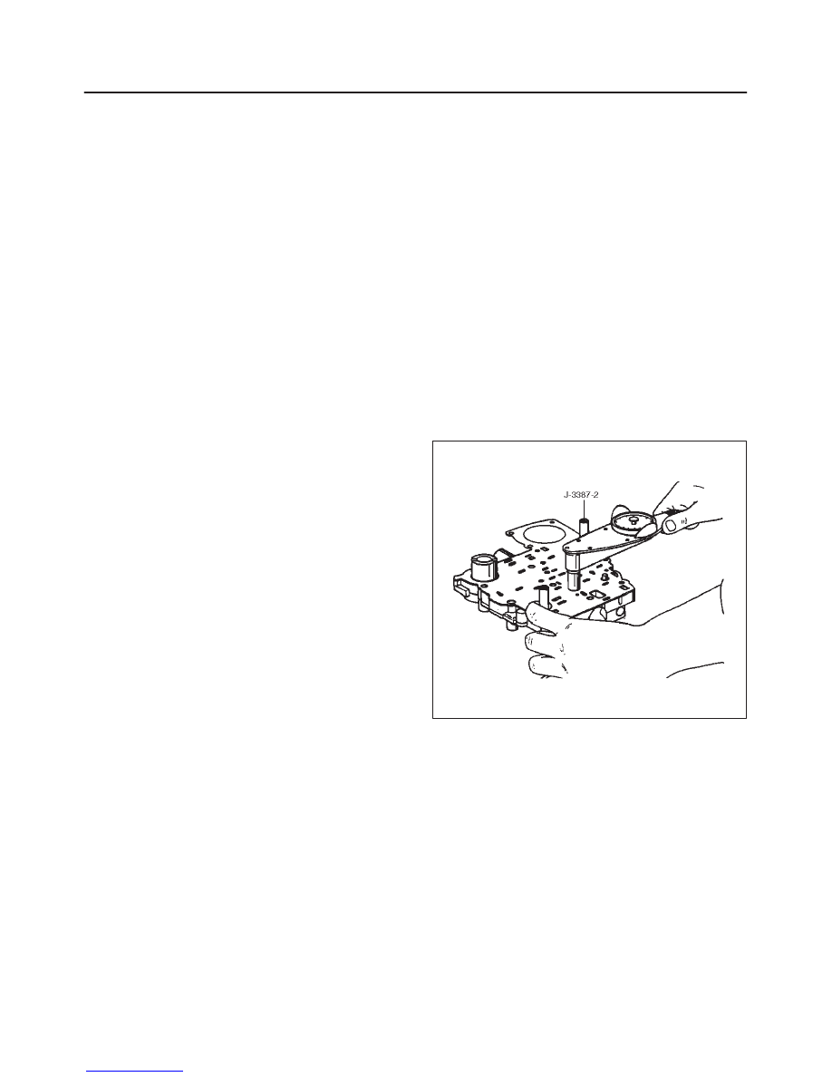
9. Install gasket (valve body/transfer plate) and transfer
plate using two J–3387–2 guide pins.
f
Install two 11mm bolts.
Torque: 13 N
•
m (113 lb in)
244RS004
f
Install gasket (transfer plate/main case).
7A–69
AUTOMATIC TRANSMISSION (4L30–E)
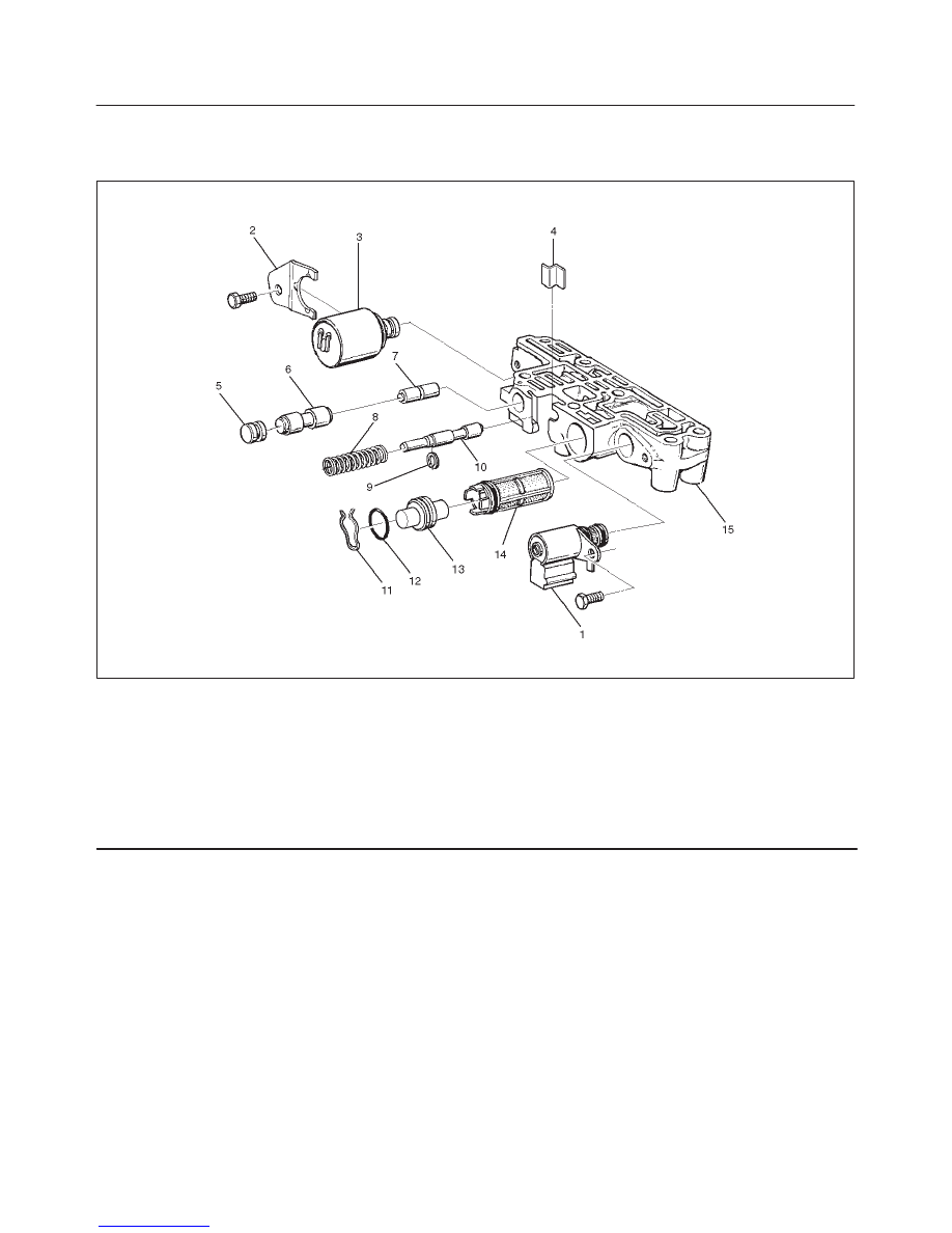
Adapter Case Valve Body
Disassembled View
243RW001
Legend
(1) Converter Clutch Solenoid Assembly
(2) Retainer
(3) Force Motor Solenoid
(4) Retainer
(5) Plug
(6) 3/4 Accumulator Valve
(7) 3/4 Accumulator Control Valve
(8) Spring
(9) Retaining Ring
(10) Feed Iimit Valve
(11) Plug Retainer
(12)
O-ring
(13) Plug
(14) Force Motor Screen Assembly
(15) Adapter Case Valve Body
Disassembly
1. Remove 11mm bolt from valve body.
f
Remove converter control solenoid assembly (1).
2. Remove 11mm bolt and retainer (2) from valve body.
f
Remove force motor solenoid (3).
3. Remove retainer (4), plug (5), 3/4 accumulator valve
(6), and 3/4 accumulator control valve (7)
4. Remove spring (8), retaining ring (9), and feed limit
valve (10).
5. Remove plug retainer (11), O-ring (12), plug (13), and
force motor screen assembly (14).
f
Use 5 mm bolt to pull plug.
Inspection and Repair
Inspect for the following, and replace any damaged or
worn parts:
1. Damage or wear to each valve.
2. Damage in oil passeges.
3. Cracks or damage to valve body.
4. Valve operations.
5. Spring fatigue.
Reassembly
1. Install force motor screen assembly (14), plug (13),
O-ring (12), and plug retainer (11).
2. Install feed limit valve (10), retaining ring (9), and
spring (8).
7A–70
AUTOMATIC TRANSMISSION (4L30–E)
3. Install 3/4 accumulator control valve (7), 3/4
accumulator valve (6), plug (5), and retainer (4).
4. Install force motor solenoid (3).
f
Place solenoid terminals pointing towards mating
face.
f
Install retainer (2) and bolt.
Torque: 10 N
•
m (87 lb in)
5. Install converter clutch solenoid assembly with two
O-rings (1) to valve body.
f
Install bolt.
Torque: 10 N
•
m (87 lb in)
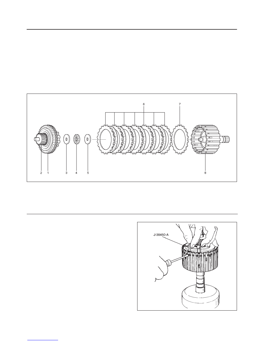
Third Clutch and Sprag Unit
Disassembled View
248RW001
Legend
(1) Retaining Ring
(2) Input Sun Gear and Sprag Unit Assembly
(3) Retaining Washer
(4) Bearing
(5) Thrust Washer
(6) Clutch Plates
(7) Third Clutch Spring Cushion Plate
(8) Third Clutch Drum Assembly
Disassembly
1. Place the third clutch drum and intermediate shaft
assembly upright, using the overdrive internal gear as
a support.
2. Locate the ends of the retaining ring. Depress one
end of the ring using a small screwdriver instead of
the depressor handle provided with the tool
J-38450-A. Slide one blade down between the third
clutch drum and the retaining ring.
3. Remove a screwdriver and repeat this step for the
other end of retaining ring.
4. Install the remaining four blades approximately (five)
notches apart using a screwdriver to depress the
retaining ring.
5. Pull up on input sun gear and sprag unit assembly (1
and 2) to release the retaining ring from third clutch
drum assembly (8).
6. Remove the tool blades.
248RX001
7A–71
AUTOMATIC TRANSMISSION (4L30–E)
7. Remove retaining washer (3), bearing (4), thrust
washer (5), and clutch plates (6 and 7) from the third
clutch drum assembly (8).
Inspection and Repair
Visual Check:
If any damage, deformation or wear is found, replace the
damaged part.
Reassembly
1. Place third clutch drum and intermediate shaft
assembly upright, using the overdrive internal gear as
a support.
2. Install third clutch spring cushion plate (7), bevel face
down.
3. Install third clutch plates (6) into third clutch drum
assembly (8). Start with the steel clutch plate and
alternate with lined plates.
4. Install thrust washer (5), bearing (4) and retaining
washer (3).
5. Fully engage the hub spline of the input sun gear and
sprag unit assembly (2) into the third clutch inner
tangs.
f
Simultaneously rotate the outer sprag race to
engage into the third clutch drum assembly (8).
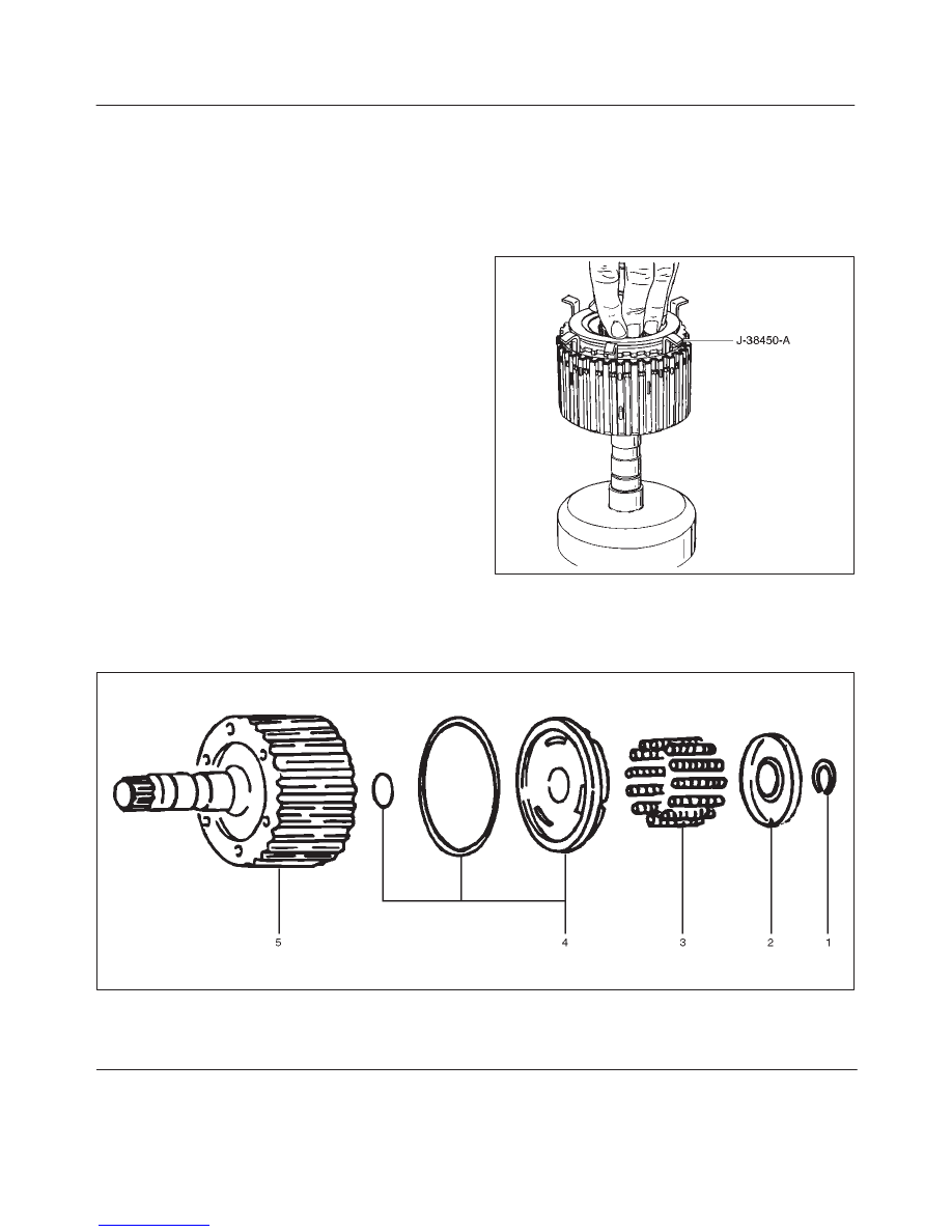
6. Place J-38450-A blades between the retaining ring
and the third clutch drum apporximately (five)
notches apart, and one blade at each end of the
retaining ring (1). Push down on sprag assembly until
the assembly is seated into the third clutch drum
assembly (8).
7. Remove the tool blades and engage retaining ring
into groove of third clutch drum.
248RX002
Third Clutch
Disassembled View
248RS006
Legend
(1) Retaining Ring
(2) Spring Seat
(3) Springs
(4) Piston Assembly
(5) Third Clutch Drum
Нет комментариевНе стесняйтесь поделиться с нами вашим ценным мнением.
Текст