Isuzu Rodeo UE. Manual — part 462
7A–64
AUTOMATIC TRANSMISSION (4L30–E)
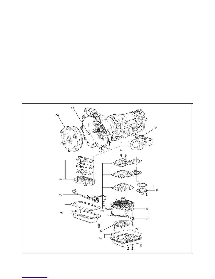
56. Connect wiring harness harness assembly (52) to
converter clutch solenoid, force motor, and 5 pin
connector.
57. Install oil pan gasket, adapter case oil pan (53), and
twelve 10 mm screws.
Torque: 11 N
•
m (96 lb in)
f
Rotate transmission, with bottom pan facing down.
58. Install mode switch (54), two 10 mm screws, selector
lever nut, and cover.
10 mm screw
Torque: 13 N
•
m (113 lb in)
Nut
Torque: 23 N
•
m (17 lb ft)
f
Adjust using setting tool, refer to Mode Switch in
this section.
59. Install O-ring (55) on turbine shaft.
60. Install torque converter (56)
The converter assembly must be replaced under any
of the following conditions:
a. Evidence of damage to the pump assembly.
b. Metal particles are found after flushing the cooler
lines.
c. External leaks in hub weld area.
d. Converter pilot broken, damaged, or poor fit into
crankshaft.
e. Converter hub scored or damaged.
f. Internal failure in stator.
g. Contamination from engine coolant.
h. Excess end play.
f
Rotate transmission, bell housing up. Spin
converter to insure proper fit.
61. Fill transmission through the overfill screw hole of oil
pan, using ATF DEXRON
–III. Refer to Changing
Transmission Fluid in this section.
241RW016
7A–65
AUTOMATIC TRANSMISSION (4L30–E)
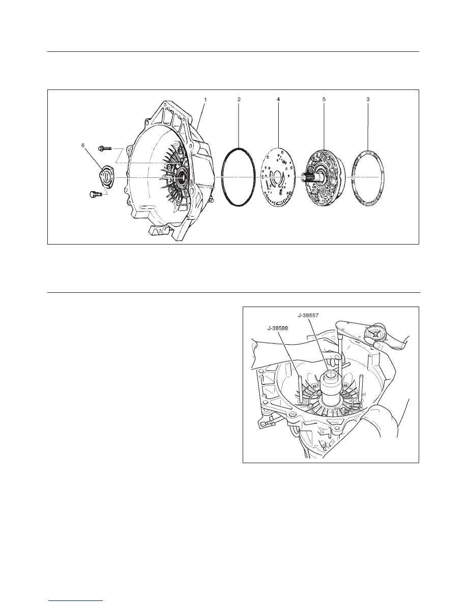
Converter Housing and Oil Pump Assembly
Disassembled View
241RW003
Legend
(1) Converter Housing
(2) Outer Seal Ring
(3) Gasket
(4) Wear Plate
(5) Oil Pump Assembly
(6) Oil Seal Ring
Disassembly
1. Remove oil pump assembly from converter housing.
2. Remove outer seal ring.
3. Remove gasket.
4. Remove wear plate.
5. Remove oil seal ring.
Inspection and Repair
Visual Check:
If any damage, deformation, or local wear is found in a
converter housing, outer seal ring, wear plate, or oil seal
ring, replace it.
Reassembly
1. Install wear plate onto oil pump assembly.
2. Install converter housing onto complete oil pump
assembly. Align with two short J–38588 guide pins on
outer bolt holes.
f
Loosely install five 13mm bolts.
f
Center converter housing using J–38557 centering
tool.
f
Tighten five inner 13mm bolts in an alternating
pattern.
Torque: 20 N
•
m (15 lb ft)
241RW002
3. Install oil seal ring (3 screws).
Torque: 3 N
•
m (26 lb in)
4. Install gasket.
5. Install outer seal ring.
7A–66
AUTOMATIC TRANSMISSION (4L30–E)
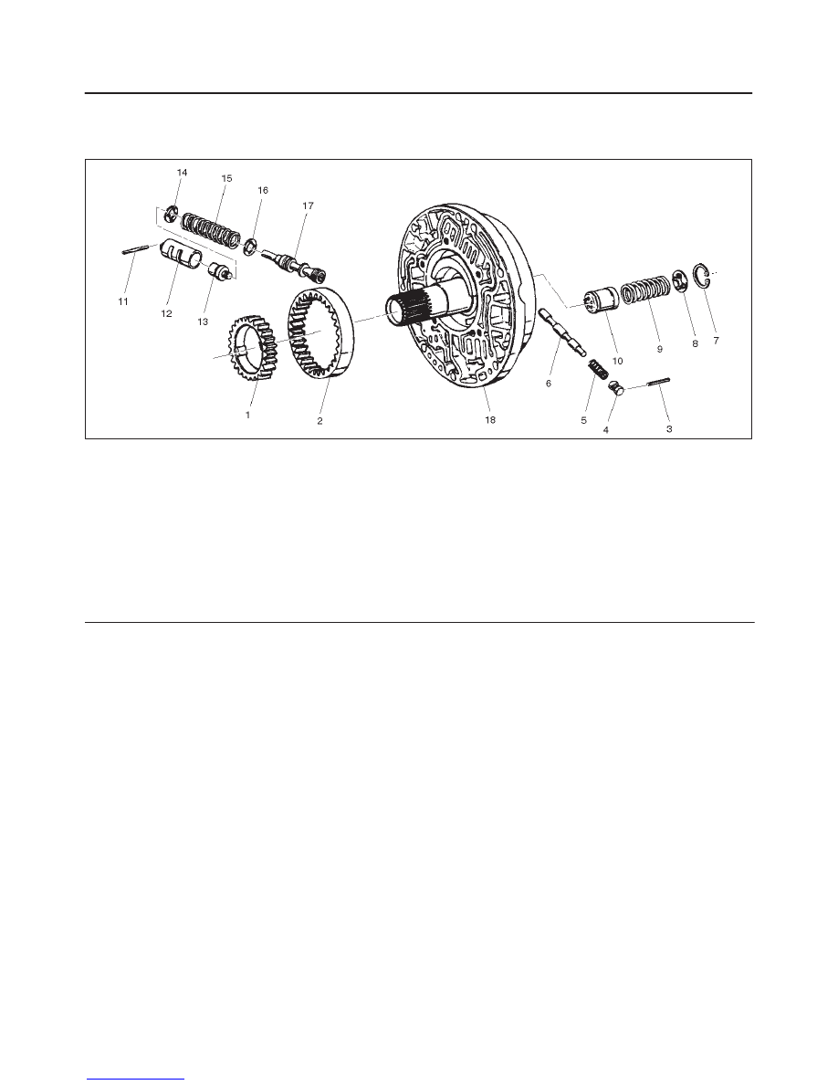
Oil Pump
Disassembled View
241RS014
Legend
(1) Oil Pump Drive Gear
(2) Oil Pump Driven Gear
(3) Pin
(4) Plug
(5) Spring
(6) Converter Clutch Control Valve
(7) Snap Ring
(8) Spring Seat
(9) Spring
(10)
Throttle Signal Accumulator Piston
(11)
Sleeve Pin
(12)
Sleeve
(13)
Boost Valve
(14)
Spring Seat
(15)
Valve Spring
(16)
Spring Seat
(17)
Pressure Regulator valve
(18)
Oil Pump Assembly
Disassembly
1. Remove oil pump drive gear (1) and driven gear (2).
2. Remove pin (3) from oil pump assembly (18).
3. Remove plug (4), spring (5), and converter clutch
control valve (6).
4. Remove snap ring (7) from oil pump assembly (18).
5. Remove spring seat (8), spring (9), and throttle signal
accumulator piston (10).
6. Remove sleeve pin (11) from oil pump assembly (18).
7. Remove sleeve (12), boost valve (13), spring seat
(14), valve spring (15), spring seat (16), and pressure
regulator valve (17).
Inspection and Repair
Visual Check:
If any damage, deformation or wear is found, replace the
damaged part.
Reassembly
1. Lubricate and preinstall pressure regulator spring
seat (16) on valve (17), with the flat side against
shoulder.
2. Install pressure regulator valve (17) and spring seat
(16) assembly, valve spring (15), and spring seat (14)
with the flat side away from spring to oil pump
assembly (18).
3. Assemble boost valve (13) into sleeve (12).
4. Install boost valve and sleeve assembly, and sleeve
pin (11) to oil pump assembly (18).
5. Install throttle signal accumulator piston (10), spring
(9), and spring seat (8), with the flat side away from
the spring, and snap ring (7) to oil pump assembly
(18).
6. Install converter clutch control valve (6), spring (5),
plug (4), and pin (3) to oil pump assembly (18).
7. Install oil pump driven gear (2) and drive gear (1).
7A–67
AUTOMATIC TRANSMISSION (4L30–E)
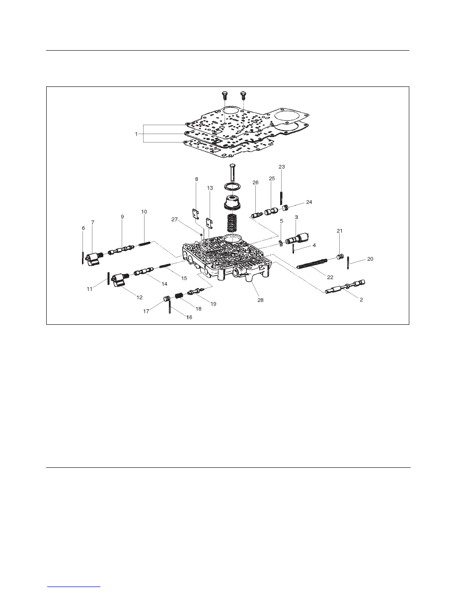
Main Case Valve Body
Disassembled View
244RS010
Legend
(1) Gaskets and Transfer Plate
(2) Manual Valve
(3) Band Control Solenoid
(4) Pin
(5) Waved Washer
(6) Spring Pin
(7) Solenoid A
(8) Retainer
(9) 1–2/3–4 Shift Valve
(10) Spring
(11) Spring Pin
(12) Solenoid B
(13) Retainer
(14) 2–3 Shift Valve
(15) Spring
(16) Spring Pin
(17) Plug
(18) Spring
(19) Low Pressure Control Valve
(20) Spring Pin
(21) Plug
(22) Band Control Screen Assembly
(23) Spring Pin
(24) Plug
(25) 1–2 Accumulator Valve
(26) 1–2 Accumulator Control Valve
(27) Check ball
(28) Main Case Valve Body
Нет комментариевНе стесняйтесь поделиться с нами вашим ценным мнением.
Текст