Isuzu Rodeo UE. Manual — part 347
6E2–143
RODEO 6VD1 3.2L ENGINE DRIVEABILITY AND EMISSIONS
Diagnostic Trouble Code (DTC) P0117 ECT Sensor Circuit Low Voltage
D06RW058
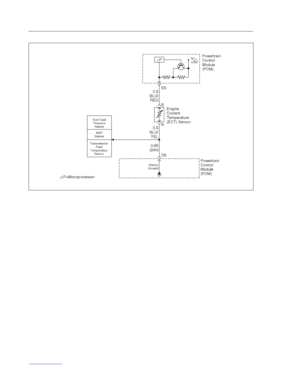
Circuit Description
The engine coolant temperature (ECT) sensor is a
thermistor mounted on a coolant crossover pipe at the
front of the engine. The powertrain control module (PCM)
applies a voltage (about 5 volts) through a pull-up resistor
to the ECT signal circuit. When the engine coolant is cold,
the sensor (thermistor) resistance is high, therefore the
PCM will measure a high signal voltage. As the engine
coolant warms, the sensor resistance becomes lower,
and the ECT signal voltage measured at the PCM drops.
With a fully warmed-up engine, the ECT signal voltage
should measure about 1.5 to 2.0 volts.
Conditions for Setting the DTC
f
Engine running time is longer than one minute.
f
The ECT sensor signal indicates an engine coolant
temperature greater than 150
°
C (302
°
F) (about 0.10
V) for a total of 50 seconds over a 100-second period.
Action Taken When the DTC Sets
f
The PCM will illuminate the malfunction indicator lamp
(MIL) the first time the fault is detected.
f
The PCM will substitute the ECT reading with a default
engine coolant temperature value. The default value
is based on start-up intake air temperature and running
time.
f
The PCM will store conditions which were present
when the DTC was set as Freeze Frame and in the
Failure Records data.
Conditions for Clearing the MIL/DTC
f
The PCM will turn the MIL “OFF” on the third
consecutive trip cycle during which the diagnostic has
been run and the fault condition is no longer present.
f
A history DTC P0117 will clear after 40 consecutive
warm-up cycles have occurred without a fault.
f
DTC P0117 can be cleared by using the Tech 2 “Clear
Info” function or by disconnecting the PCM battery
feed.
Diagnostic Aids
Check for the following conditions:
f
Poor connection at PCM – Inspect harness connectors
for backed-out terminals, improper mating, broken
locks, improperly formed or damaged terminals, and
poor terminal-to-wire connection.
f
Damaged harness – Inspect the wiring harness for
damage. If the harness appears to be OK, observe the
ECT display on the Tech 2 while moving connectors
and wiring harnesses related to the ECT sensor. A
change in the ECT display will indicate the location of
the fault.
If DTC P0117 cannot be duplicated, the information
included in the Failure Records data can be useful in
determining vehicle mileage since the DTC was last set.
If it is determined that the DTC occurs intermittently,
performing the DTC P1114 Diagnostic Chart may isolate
the cause of the fault.
6E2–144
RODEO 6VD1 3.2L ENGINE DRIVEABILITY AND EMISSIONS
Test Description
Number(s) below refer to the step number(s) on the
Diagnostic Chart.
2. Verifies that the fault is present.
3. If DTC P0117 can be repeated only by duplicating
the Failure Records conditions, refer to the
“Temperature vs. Resistance Values” table. The
table may be used to test the ECT sensor at various
temperatures to evaluate the possibility of a
“shifted” sensor that may be shorted above or below
a certain temperature. If this is the case, replace
the ECT sensor. If the ECT sensor appears to be
OK, the fault is intermittent; refer to
Diagnostic Aids.
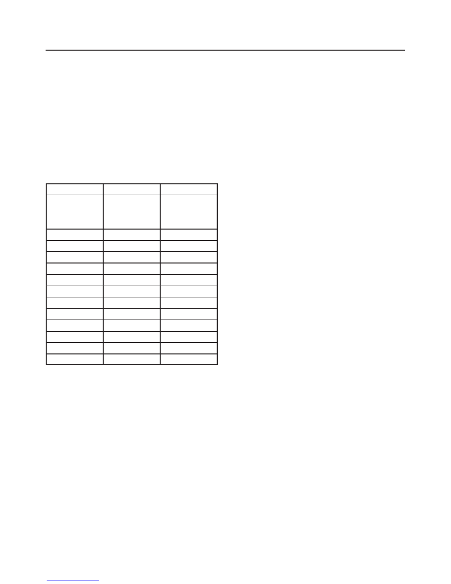
Engine Coolant Temperature Sensor
°
C
°
F
OHMS
Temperature
vs. Resistance
Values
(approximate)
100
212
177
80
176
332
60
140
667
45
113
1188
35
95
1802
25
77
2796
15
59
4450
5
41
7280
–5
23
12300
–15
5
21450
–30
–22
52700
–40
–40
100700

6E2–145
RODEO 6VD1 3.2L ENGINE DRIVEABILITY AND EMISSIONS
DTC P0117 – ECT Sensor Low Voltage
Step
Action
Value(s)
Yes
No
1
Was the “On-Board Diagnostic (OBD) System Check”
performed?
—
Go to
Step 2
Go to
OBD
System
Check
2
1. Ignition “ON,” engine “OFF.”
2. Observe the “Eng Cool Temp” display on the Tech 2.
Is the “Eng Cool Temp” below the specified value?
139
°
C
(282
°
F)
Go to
Step 4
Go to
Step 3
3
1. Ignition “ON,” engine “OFF.”
2. Review and record Tech 2 Failure Records data.
3. Operate the vehicle within Failure Records
conditions as noted.
4. Using a Tech 2, monitor “DTC” info for DTC P0117.
Does the Tech 2 indicate DTC P0117 failed this
ignition?
—
Go to
Step 4
Refer to
Diagnostic
Aids
4
1. Disconnect the ECT sensor electrical connector.
2. Observe the “Eng Cool Temp” display on the Tech 2.
Is the “Eng Cool Temp” at the specified value?
–39
°
C
(–38
°
F)
Go to
Step 6
Go to
Step 5
5
1. Ignition “OFF.”
2. Disconnect the PCM and check the ECT signal
circuit for a short to ground or a short to the sensor
ground circuit.
3. If the ECT signal circuit is shorted. repair it as
necessary.
Was the ECT signal circuit shorted to ground?
—
Verify repair
Go to
Step 7
6
Replace the ECT sensor.
Is the action complete?
—
Verify repair
—
7
Replace the PCM.
IMPORTANT: The replacement PCM must be
programmed. Refer to
On-Vehicle Service in
Powertrain Control Module and Sensors for
procedures.
And also refer to latest service bulletin.
Check to see if the Latest software is released or not.
And then Down Load the LATEST PROGRAMMED
SOFTWARE to the replacement PCM.
Is the action complete?
—
Verify repair
—
6E2–146
RODEO 6VD1 3.2L ENGINE DRIVEABILITY AND EMISSIONS
Diagnostic Trouble Code (DTC) P0118 ECT Sensor Circuit High Voltage
D06RW058
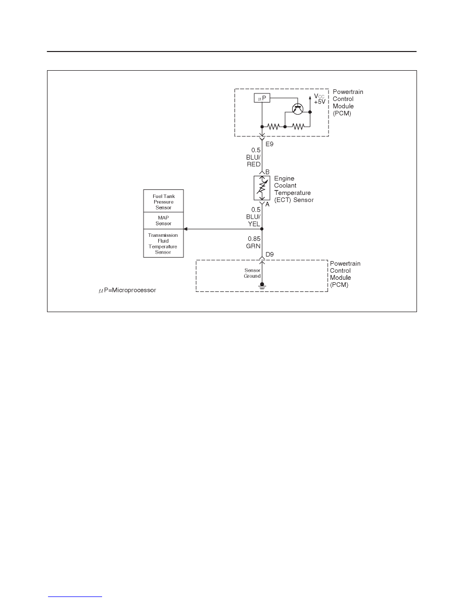
Circuit Description
The engine coolant temperature (ECT) sensor is a
thermistor mounted in on a coolant crossover pipe at the
front of the engine. The powertrain control module (PCM)
applies a voltage (about 5 volts) through a pull-up resistor
to the ECT signal circuit. When the engine coolant is cold,
the sensor (thermistor) resistance is high, therefore the
PCM will measure a high signal voltage. As the engine
coolant warms, the sensor resistance becomes less, and
the ECT signal voltage measured at the PCM drops. With
a fully warmed-up engine, the ECT signal voltage should
measure about 1.5 to 2.0 volts.
Conditions for Setting the DTC
f
Engine running time is longer than 1.5 minutes.
f
The ECT sensor signal indicates an engine coolant
temperature of –39
°
C (–38
°
F) or less (about 5 volts)
for a total of 50 seconds over a 100-second period.
Action Taken When the DTC Sets
f
The PCM will illuminate the malfunction indicator lamp
(MIL) the first time the fault is detected.
f
The PCM will substitute the ECT reading with a default
engine coolant temperature value. The default value
is based on start-up intake air temperature and running
time.
f
The PCM will store conditions which were present
when the DTC was set as Freeze Frame and in the
Failure Records data.
Conditions for Clearing the MIL/DTC
f
The PCM will turn the MIL “OFF” on the third
consecutive trip cycle during which the diagnostic has
been run and the fault condition is no longer present.
f
A history DTC P0118 will clear after 40 consecutive
warm-up cycles have occurred without a fault.
f
DTC P0118 can be cleared by using the Tech 2 “Clear
Info” function or by disconnecting the PCM battery
feed.
Diagnostic Aids
Check for the following conditions:
f
Poor connection at PCM – Inspect harness connectors
for backed-out terminals, improper mating, broken
locks, improperly formed or damaged terminals, and
poor terminal-to-wire connection.
f
Damaged harness – Inspect the wiring harness for
damage. If the harness appears to be OK, observe the
ECT display on the Tech 2 while moving connectors
and wiring harnesses related to the ECT sensor. A
change in the ECT display will indicate the location of
the fault.
If DTC P0118 cannot be duplicated, the information
included in the Failure Records data can be useful in
determining vehicle mileage since the DTC was last set.
If it is determined that the DTC occurs intermittently,
performing the DTC P1115 Diagnostic Chart may isolate
the cause of the fault.
Нет комментариевНе стесняйтесь поделиться с нами вашим ценным мнением.
Текст