Isuzu Rodeo UE. Manual — part 348

6E2–147
RODEO 6VD1 3.2L ENGINE DRIVEABILITY AND EMISSIONS
Test Description
Number(s) below refer to the step number(s) on the
Diagnostic Chart.
2. Verifies that the fault is present.
3. If DTC P0118 can be repeated only by duplicating
the Failure Records conditions, refer to the
“Temperature vs. Resistance Value” table. The
table may be used to test the ECT sensor at various
temperatures to evaluate the possibility of a
“shifted” sensor that may be shorted above or below
a certain temperature. If this is the case, replace
the ECT sensor. If the ECT sensor appears to be
OK, the fault is intermittent; refer to
Diagnostic Aids.
Engine Coolant Temperature Sensor
°
C
°
F
OHMS
Temperature
vs. Resistance
Values
(approximate)
100
212
177
80
176
332
60
140
667
45
113
1188
35
95
1802
25
77
2796
15
59
4450
5
41
7280
–5
23
12300
–15
5
21450
–30
–22
52700
–40
–40
100700
DTC P0118 – ECT Sensor Circuit High Voltage
Step
Action
Value(s)
Yes
No
1
Was the “On-Board Diagnostic (OBD) System Check”
performed?
—
Go to
Step 2
Go to
OBD
System
Check
2
1. Ignition “ON,” engine “OFF.”
2. Observe the “Eng Cool Temp” display on the Tech 2.
Is the “Eng Cool Temp” below the specified value?
–39
°
C
(–38
°
F)
Go to
Step 4
Go to
Step 3
3
1. Ignition “ON,” engine “OFF.”
2. Review and record Tech 2 Failure Records data.
3. Operate the vehicle within Failure Records
conditions as noted.
4. Using a Tech 2, monitor the “DTC” info for DTC
P0118.
Does the Tech 2 indicate DTC P0118 failed?
—
Refer to
Test
Description
Refer to
Diagnostic
Aids
4
1. Disconnect the ECT sensor electrical connector.
2. Jumper the ECT signal circuit and the sensor
ground circuit together at the ECT sensor harness
connector.
3. Observe the “Eng Cool Temp” display on the Tech 2.
Is the “Eng Cool Temp” at the specified value?
140
°
C
(284
°
F)
Go to
Step 6
Go to
Step 5
5
1. Jumper the ECT signal circuit at the ECT sensor
harness connector to chassis ground.
2. Observe the “Eng Cool Temp” display on the Tech 2.
Is the “Eng Cool Temp” at the specified value?
140
°
C
(284
°
F)
Go to
Step 7
Go to
Step 8
6
Check for poor connections at the ECT sensor and
replace terminals if necessary.
Did any terminals require replacement?
—
Verify repair
Go to
Step 10

6E2–148
RODEO 6VD1 3.2L ENGINE DRIVEABILITY AND EMISSIONS
DTC P0118 – ECT Sensor Circuit High Voltage
(Cont'd)
Step
No
Yes
Value(s)
Action
7
1. Ignition “OFF.”
2. Disconnect the PCM, and check the ECT sensor
ground circuit for an open.
3. If the ECT sensor ground circuit is open, repair it as
necessary.
Was the ECT sensor ground circuit open?
—
Verify repair
Go to
Step 9
8
1. Ignition “OFF.”
2. Disconnect the PCM, and check the ECT signal
circuit for an open.
3. If the ECT sensor signal circuit is open, repair it as
necessary.
Was the ECT signal circuit open?
—
Verify repair
Go to
Step 9
9
Check for a poor sensor ground or ECT signal circuit
terminal connection at the PCM and replace
terminal(s) if necessary.
Did any of the terminals need to be replaced?
—
Verify repair
Go to
Step 11
10
Replace the ECT sensor.
Is the action complete?
—
Verify repair
—
11
Replace the PCM.
IMPORTANT: The replacement PCM must be
programmed. Refer to
On-Vehicle Service in
Powertrain Control Module and Sensors for
procedures.
And also refer to latest service bulletin.
Check to see if the Latest software is released or not.
And then Down Load the LATEST PROGRAMMED
SOFTWARE to the replacement PCM.
Is the action complete?
—
Verify repair
—
6E2–149
RODEO 6VD1 3.2L ENGINE DRIVEABILITY AND EMISSIONS
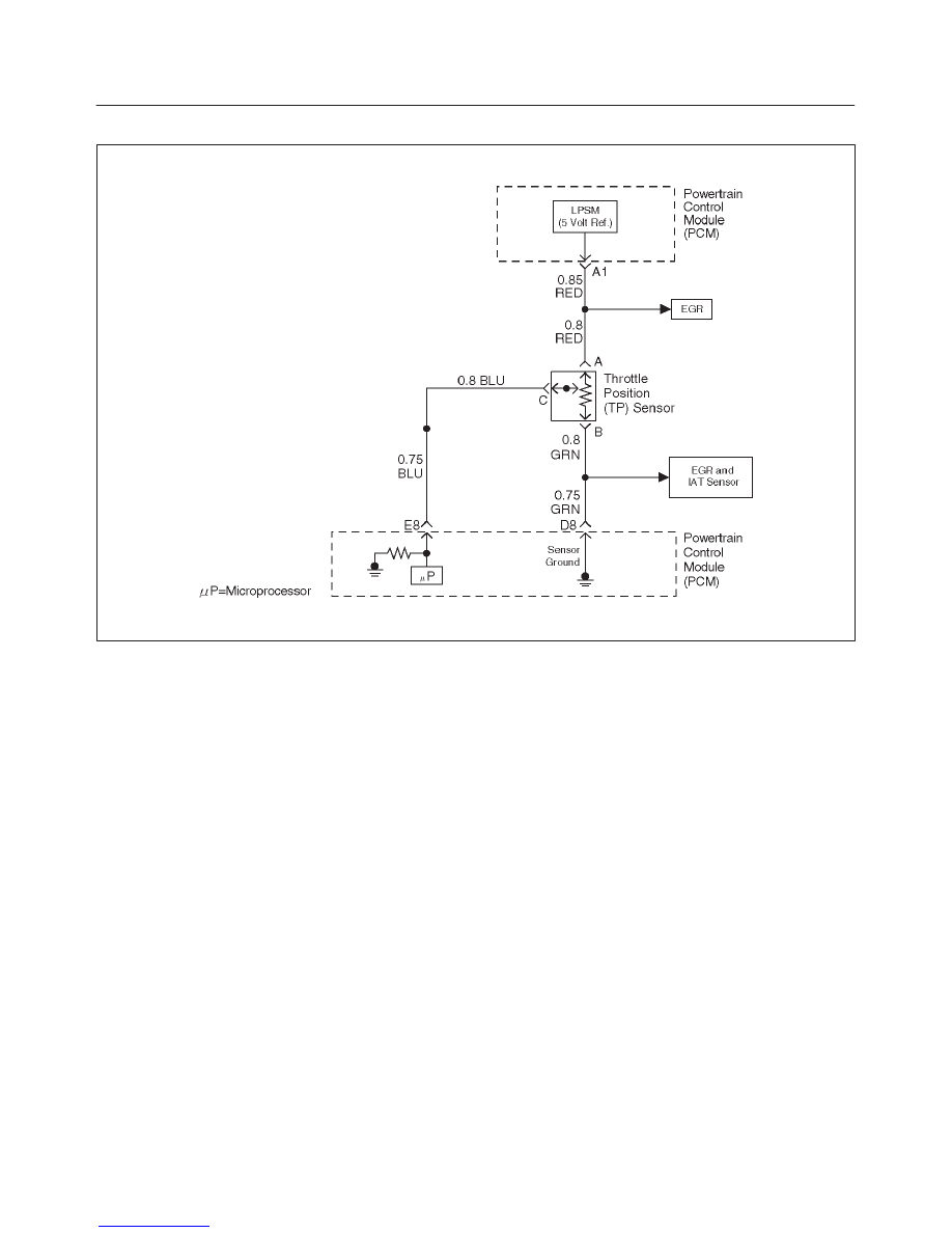
Diagnostic Trouble Code (DTC) P0121 TP System Performance
D06RW059
Circuit Description
The throttle position (TP) sensor circuit provides a voltage
signal that changes relative to throttle blade angle. The
signal voltage will vary from about 0.6 volts at closed
throttle to about 4.5 volts at wide open throttle (WOT).
The TP signal is one of the most important inputs used by
the powertrain control module (PCM) for fuel control and
many of the PCM-controlled outputs. The PCM monitors
throttle position and compares actual throttle position
from the TP sensor to a predicted TP value calculated
from engine speed. If the PCM detects an out-of-range
condition, DTC P0121 will set.
Conditions for Setting the DTC
f
The engine is running.
f
No MAP DTCs, or P0121, P0122, P1122, P0123 DTCs
are set.
f
MAP reading is below 55 kPa.
f
Throttle is steady, throttle angle is changing less than
1%.
f
Predicted throttle angle is not close to actual throttle
angle.
f
Above conditions are present for a total of 12.5
seconds over a 25-second period of time.
Action Taken When the DTC Sets
f
The PCM will illuminate the malfunction indicator lamp
(MIL) after the second consecutive trip in which the
fault is detected.
f
The PCM will store conditions which were present
when the DTC was set as Freeze Frame and in the
Failure Records data.
f
The PCM will use a default throttle position based on
mass air flow and RPM.
Conditions for Clearing the MIL/DTC
f
The PCM will turn the MIL “OFF” on the third
consecutive trip cycle during which the diagnostic has
been run and the fault condition is no longer present.
f
A history DTC P0121 will clear after 40 consecutive
warm-up cycles have occurred without a fault.
f
DTC P0121 can be cleared by using the Tech 2 “Clear
info ” function or by disconnecting the PCM battery
feed.
Diagnostic Aids
Check for the following conditions:
f
Skewed MAP signal or faulty MAP sensor – An
incorrect MAP signal may cause the PCM to incorrectly
calculate the predicted TP sensor value during high
engine load situations. Check for an unusually low
MAP reading. This condition can cause DTC P0121 to
be set.
f
The TP Sensor shares a 5 Volt reference with the EGR
Valve.
If these codes are also set, it could indicate a
problem with the 5 Volt reference circuit or
components itself.
f
The TP Sensor share a ground with the EGR Valve and
the IAT Sensor.

6E2–150
RODEO 6VD1 3.2L ENGINE DRIVEABILITY AND EMISSIONS
f
Poor connection at PCM – Inspect harness connectors
for backed-out terminals, improper mating, broken
locks improperly formed or damaged terminals, and
poor terminal-to-wire connection.
f
Damaged harness – Inspect the wiring harness for
damage. If the harness appears to be OK, observe the
ECT display on the Tech 2 while moving connectors
and wiring harnesses related to the sensor. A change
in the display will indicate the location of the fault.
If DTC P0121 cannot be duplicated, the information
included in the Failure Records data can be useful in
determining vehicle mileage since the DTC was last set.
If it is determined that the DTC occurs intermittently,
performing the DTC P1122 and DTC P1121 Diagnostic
Charts may isolate the cause of the fault.
DTC P0121 –TP System Performance
Step
Action
Value(s)
Yes
No
1
Was the “On-Board Diagnostic (OBD) System Check”
performed?
—
Go to
Step 2
Go to
OBD
System
Check
2
1. Ignition “ON,” engine not running.
2. Observe the MAP reading on the Tech 2.
Is the MAP reading less than the specified value?
65 kPa
Go to
Step 3
Go to
Step 6
3
1. Disconnected the MAP sensor.
2. Connect a test light between the 5 volt reference “A”
circuit and the MAP signal circuit at the MAP sensor
harness connector.
3. Observe the MAP reading on the Tech 2.
Is the MAP reading less than the specified value? (If no,
start with diagnosis chart for other sensors in the circuit
and see if 5V returns.)
65 kPa
Go to
Step 5
Go to
Step 4
4
1. Check the MAP signal circuit between the PCM and
the MAP sensor for an open, short to ground, or
short to the MAP ground circuit.
2. If the MAP signal circuit is open or shorted, repair it
as necessary.
Was the MAP signal circuit open or shorted?
—
Verify repair
Go to
Step 12
5
Replace the MAP sensor.
Is the action complete?
—
Verify repair
—
6
Observe the TP angle reading on the Tech 2 while
slowly opening the throttle.
Does the TP angle increase steadily and evenly from
the closed throttle value to the wide open throttle
value?
Closed
throttle = 0%
Wide open
throttle =
100%
Refer to
Diagnostic
Aids
Go to
Step 7
7
1. Disconnect the TP sensor.
2. Observe the TP sensor reading on the Tech 2.
Is the TP sensor reading near the specified value?
0 V
Go to
Step 8
Go to
Step 9
8
1. Connect a test light between the 5 volt reference “A”
circuit and the TP sensor signal circuit at the TP
sensor harness connector.
2. Observe the TP sensor reading on the Tech 2.
Is the TP sensor reading at the specified value?
5 V
Go to
Step 11
Go to
Step 10
Нет комментариевНе стесняйтесь поделиться с нами вашим ценным мнением.
Текст