Isuzu Rodeo UE. Manual — part 574

8D–144
WIRING SYSTEM
Parts Location
D08RX069
Legend
(1) Cruise Pump & Actuator
(2) C–26
(3) H–12
(4) H–19
(5) (PCM) C–3
(6) Cruise Control Unit
(7) B–18
(8) I–31
(9) I–9
(10) I–46
(11) Starter SW
(12) I–18
(13) I–6
(14) I–14
(15) H–15, H–16, H–31, H–32
(16) Clutch Switch
(17) Brake Switch
(18) M–10
(19) Mode Switch
(20) M–16
(21) H–10
(22) B–8
(23) Throttle Valve

8D–145
WIRING SYSTEM
Diagnosis
The cruise control unit uses the cruise main indicator light
and diagnosis the failure, when the control unit detects
abnormality on the table below.
PART
POSSIBLE CAUSE
DETECTION PERIOD
DTC
Motor system short circuit
Energizing motor
1-1
Clutch system open circuit
Energizing clutch
1-2
Actuator
Clutch system open circuit
Energizing clutch
1-2
Mechanical defect
Cruise controlling
1-3
Close side of motor system open circuit
Cruise controlling
1-1
Cruise control unit
Close side of motor system open circuit
While starter SW on
1-4
Cruise control unit
Clutch output abnormality
While starter SW on
1-4
Vehicle speed sensor
Signal of vehicle speed disconnection
Cruise controlling
2-1
Vehicle s eed sensor
Signal of vehicle speed abnormality
Cruise controlling
2-1
Switch
Turning on switch at all times
While starter SW on
3-1
Switch
Turning on switch at the same time
While starter SW on
3-1
DTC : Diagnostic Trouble Code
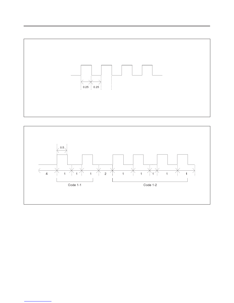
DTC Display Condition
1. While starter switch on and vehicle speed is 0 km/h,
the DTC output begins in top priority by cancel switch
turn on and off being repeated three times for 2 sec.
while cruise main switch pushing on, and stops the
DTC output whether vehicle speed is more than 10
km/h or the resume switch is turned on.
2. The cruise control unit outputs the DTC(s) in order
from small figure of the code.
3. The header of display of DTC(s) is assumed 4 sec.,
and it is 2 sec. between different king of codes.
4. The DTC(s) are erased with the starter switch turned
off.
8D–146
WIRING SYSTEM
DTC Display Format
1. When no DTCs are detected. (The unit : sec.)
F08RW003
2. When two or more DTCs are detected. (The unit : sec.)
F08RW004

8D–147
WIRING SYSTEM
Diagnosis
DTC 1–1 Motor System Short Circuit
Step
Action
Value(s)
Yes
No
1
1. Turn the starter switch off.
2. Disconnect the actuator connector C-26.
3. Measure resistance between actuator side
connector terminal 1 and 2.
NOTE: If the control plate position is fully opened or
fully closed, resistance can not be measured.
Is the resistance within range specified in the value(s)
column?
More than
4.2
W
Go to Step 2
Replace the
actuator
2
Measure continuity between harness side connector
C-26 terminal 1 and the ground, terminal 2 and the
ground, and terminals 1 and 2.
Are the result same as specified in the value(s)
column?
No continuity
Replace the
control unit
Repair or
replace the
harness
DTC 1–2 Clutch System Open or Short Circuit
Step
Action
Value(s)
Yes
No
1
1. Turn the starter switch off.
2. Disconnect the actuator connector C-26.
3. Measure resistance between actuator side
connector terminal 3 and 4.
Is the resistance within range specified in the value(s)
column?
34.7 – 42.4
W
Go to Step 2
Replace the
actuator
2
1. Disconnect the brake switch connector I-18.
2. Check continuity between switch side connector
terminal 2 and 3.
Is there continuity between terminals?
—
Go to Step 3
Adjust or
replace the
switch
3
1. Reconnect the brake switch connector I-18
2. Check continuity between harness side connector
B-18 terminal 6 and I-18 terminal 3, C-26 terminal 4
and B-18 terminal 8.
Is there continuity between terminals?
—
Go to Step 4
Repair open
circuit
4
Check continuity between harness side connector
C-26 terminal 3 and ground, C-26 terminal 4 and
ground, B-18 terminals 6 and the ground.
Are the results same as specified in the value(s)
column?
No continuity
Replace the
control unit
Repair short
circuit
Нет комментариевНе стесняйтесь поделиться с нами вашим ценным мнением.
Текст