Isuzu Rodeo UE. Manual — part 575

8D–148
WIRING SYSTEM
DTC 1–3 Mechanical Defect
Step
Action
Value(s)
Yes
No
1
1. Turn the starter switch off.
2. Disconnect the actuator connector C-26.
3. Connect the battery positive terminal to the actuator
side connector terminal 3 and the battery negative
terminal to terminal 4.
Does the control plate move by hand?
—
Replace the
actuator
Go to Step 2
2
Connect the battery positive terminal to the actuator
side connector terminal 1 and 3, and the battery
negative terminal to terminal 2 and 4.
Do the control plate move to full open side?
—
Go to Step 3
Replace the
actuator
3
Connect the battery positive terminal to the actuator
side connector terminal 2 and 3, and the battery
negative terminal to terminal 1 and 4.
Does the control plate move to full close side?
—
Go to Step 4
Replace the
actuator
4
Check continuity between harness side connector
C-26 terminal 1 and B-18 terminal 7, C-26 terminal 2
and B-18 terminal 15.
Is there continuity between terminals?
—
Replace the
control unit
Repair or
replace
harness
DTC 1–4 Close Side of Motor System Open Circuit
Step
Action
Value(s)
Yes
No
1
1. Turn the starter switch off.
2. Disconnect the actuator connector C-26.
3. Measure resistance between actuator side
connector terminal 1 and 2.
NOTE: If the control plate position is fully opened or
fully closed, resistance can not be measured.
Is the resistance within range specified in the value(s)
column?
More than
4.2
W
Go to Step 2
Replace the
actuator
2
Measure continuity between harness side connector
C-26 terminal 2 and B-18 terminal 15, C-26 terminal 1
and B-18 terminal 7.
Is there continuity between terminals?
—
Replace the
control unit
Repair or
replace the
harness
8D–149
WIRING SYSTEM
Anti–Lock Brake System (ABS)
General Description
The circuit consists of the starter switch, stoplight switch
EHCU wheel speed sensor, ABS warning light, BRAKE
warning light, and data link connector.
When the service brake is applied while in the running
mode, the EHCU (Electronic Hydraulic Control Unit)
judges which wheel is about to lock by using the wheel
rotation speed signals sent from the three wheel speed
sensors at the front wheels and rear differential. And the
brake fluid pressure applied to the four wheels is
controlled by the EHCU to prevent the wheels from
locking.
Based on the wheel rotation speed signals input from the
wheel speed sensor, the EHCU sends out signals to the
hydraulic unit to increase, maintain or decrease the brake
fluid pressure. The EHCU uses these signals to control
the fluid pressure which is applied to the front and rear
wheels.
Refer to Brake Control System in Brakes section in detail.
8D–150
WIRING SYSTEM
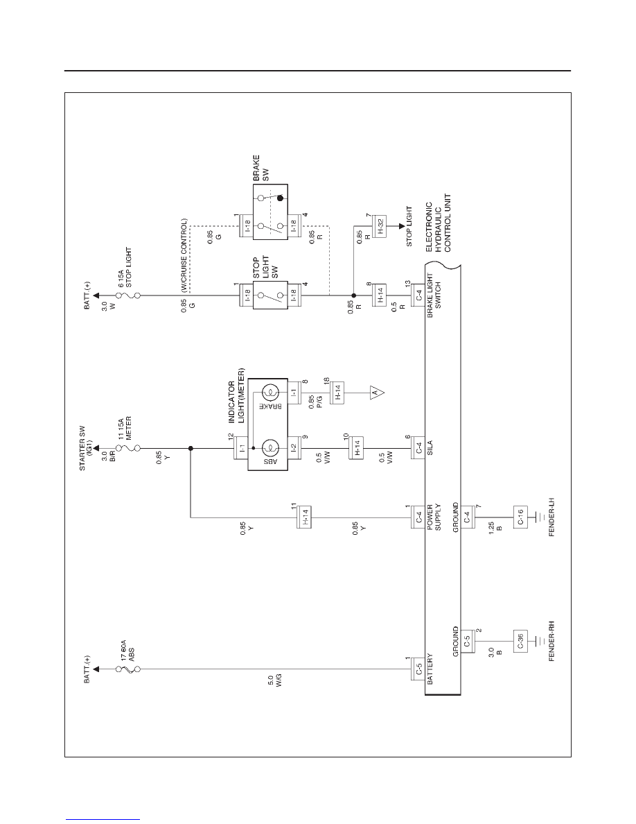
Circuit Diagram–1
D08RX108
8D–151
WIRING SYSTEM
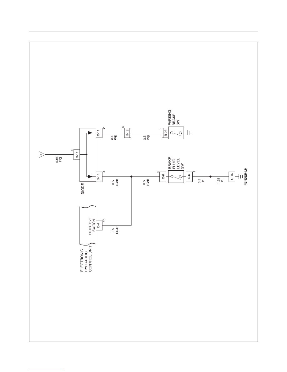
Circuit Diagram–2
D08RX110
Нет комментариевНе стесняйтесь поделиться с нами вашим ценным мнением.
Текст