Isuzu Rodeo UE. Manual — part 143
6A–61
ENGINE MECHANICAL (X22SE 2.2L)
Removal
1. Remove two bolts and remove ignition cable cover (1)
from cylinder head cover (3).
2. Disconnect ignition cable and remove spark plag (2).
3. Disconnect ignition cable from ignition plug.
4. Disconnect camshaft angle sensor harness and
crankshaft angle sensor harness from behind
generator.
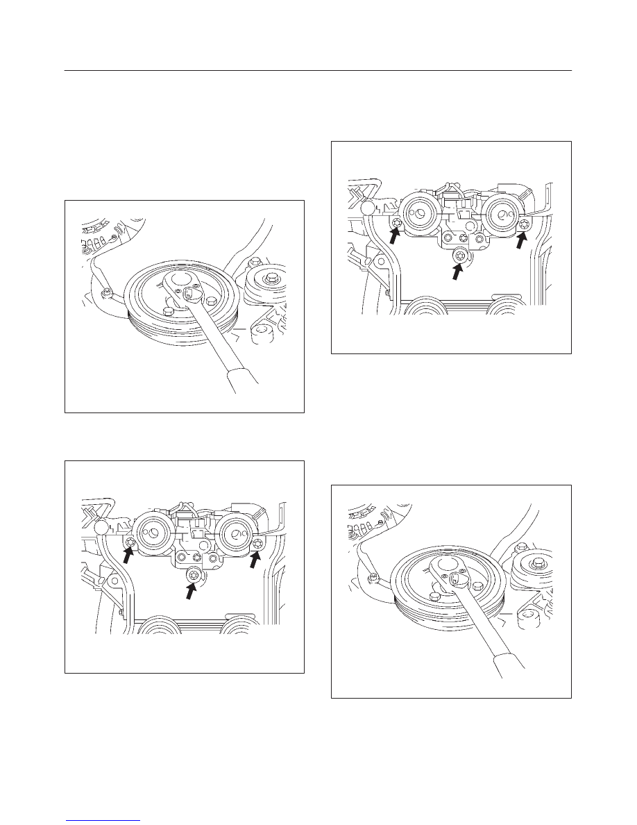
5. Remove four bolts and remove the crankshaft pulley.
020RW014
6. Remove timing belt front cover.
7. Loose fixing bolt of timing belt rear cover, then
remove the camshaft angle sensor.
020RW012
8. Remove ten cylinder head cover fixing bolts and
remove the cylinder head cover.
Installation
1. Install the camshaft angle sensor and tighten timing
rear cover bolt.
Torque: 8 N·m (5.9 lb ft)
020RW012
2. Install the cylinder head cover and tighten bolts to the
specified torque.
Torque: 8 N·m (5.9 lb ft)
3. Install the timing belt front cover then tighten fixing
bolts to the specified torque.
Torque: 6 N·m (4.4 lb ft)
4. Install the crankshaft pulley, tighten fixing bolts to the
specified torque.
Torque: 20 N·m (14 lb ft)
020RW014
6A–62
ENGINE MECHANICAL (X22SE 2.2L)
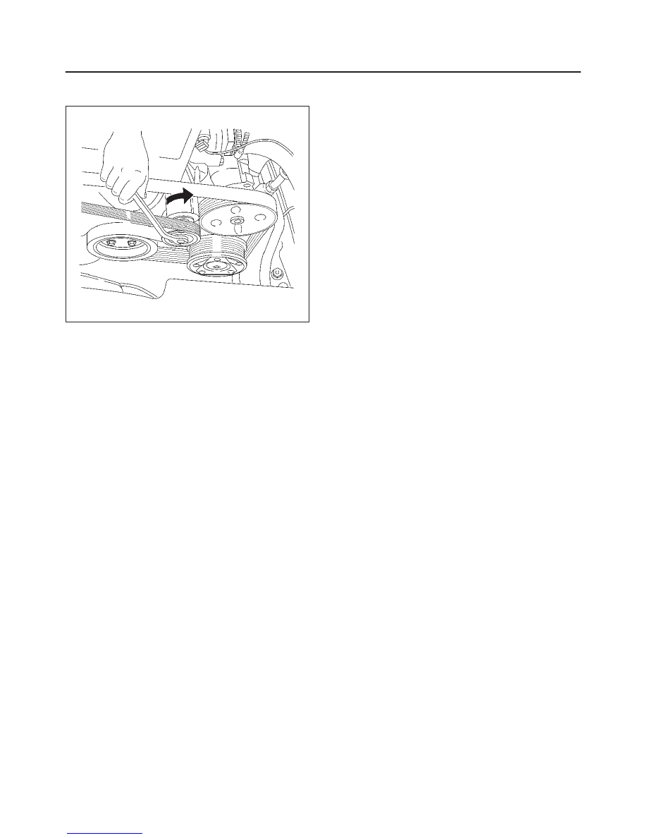
5. Move drive belt tensioner to loose side using wrench
then install the drive belt to normal position.
033RW001
6. Connect ignition cable to ignition plug.
7. Install ignition cable cover to cylinder head cover and
tighten two bolts to the specified torque.
Torque: 3 N·m (2 lb ft)
6A–63
ENGINE MECHANICAL (X22SE 2.2L)
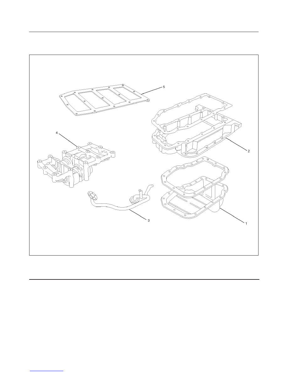
Balance Unit Assembly
Balance Unit Assembly Associated Parts
051RW012
Legend
(1) Oil Pan
(2) Oil Pan Support
(3) Oil Strainer
(4) Balance Unit Assembly
(5) Shim
6A–64
ENGINE MECHANICAL (X22SE 2.2L)
Disassembly
1. Remove the oil pan.
2. Remove the oil pan support.
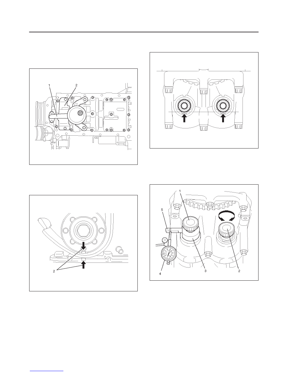
3. Remove the oil strainer (1) from oil pump and the oil
baffle plate (2).
051RW009
Adjustment
1. Turn crankshaft in engine rotational direction to
alignment mark (2) 1st cylinder “TDC”.
014RW066
2. In this crankshaft position, the flattened side (arrows)
of both balancer shafts must face downward and
must be on a horizontal line.
051RW010
3. Screw measuring device J–43038 (3) with long
knurled bolt (1) into 1st balancer shaft (intake side)
and tighter hard–tight measuring arm (5) must point in
“9 o’clock” direction shown in this illustration.
Install dial gauge holder with dial gauge (4) on
cylinder block.
051RW007
Нет комментариевНе стесняйтесь поделиться с нами вашим ценным мнением.
Текст