Isuzu Rodeo UE. Manual — part 397

6E2–343
RODEO 6VD1 3.2L ENGINE DRIVEABILITY AND EMISSIONS
8. The following chart can be used to check the
sending unit:
DTC P0462– Fuel Level Sensor Circuit –Low Voltage
Step
Action
Value(s)
Yes
No
1
Was the “On-Board Diagnostic (OBD) System Check”
performed?
—
Go to
Step 2
Go to
OBD
System
Check
2
Were any ECT or MAP DTCs set? (ECT and MAP
Sharing Ground with PCM term D9)
—
Go to other
DTC chart
Go to
Step 3
3
1. Disconnected the fuel level sensor harness from its
connector at the fuel tank.
2. Ignition “ON,” engine “OFF.”
3. Using a DVM, measure the voltage between the
sensor harness positive and ground wires.
Is the voltage approximately equal to the specified
value?
5 V
Go to
Step 7
Go to
Step 4
4
1. Ignition “ON,” engine “OFF.”
2. With a DVM, backprobe the PCM connector at the
terminal which supplies 5 volts to the fuel level
sensor.
Is the voltage approximately equal to the specified
value?
5 V
Go to
Step 5
Go to
Step 10
5
1. Ignition “ON,” engine “OFF.”
2. Fuel level sensor disconnected from wiring
harness.
3. With a DVM, probe the 5-volt supply wire at the
sensor harness.
Is the voltage approximately equal to the value
measured in Step 4?
—
Go to
Step 6
Go to
Step 10
6
Check for open or high resistance connection in the
ground wire between the PCM and the fuel level
sensor.
Is the action complete?
—
Verify repair
—
7
Remove the fuel level sensor and check the following:
f
Does the arm move freely?
f
Are the wires open or intermittently open when
wiggled?
f
Do the resistance values match the specification
chart?
Was a problem found?
—
Go to
Step 8
Go to
Step 10
8
Replace the fuel level sensor.
Is the action complete?
—
Verify repair
—

6E2–344
RODEO 6VD1 3.2L ENGINE DRIVEABILITY AND EMISSIONS
DTC P0462– Fuel Level Sensor Circuit –Low Voltage
(Cont'd)
Step
No
Yes
Value(s)
Action
9
Replace the PCM.
IMPORTANT: The replacement PCM must be
programmed. Refer to
On-Vehicle Service in
Powertrain Control Module and Sensors for
procedures.
And also refer to latest service bulletin.
Check to see if the Latest software is released or not.
And then Down Load the LATEST PROGRAMMED
SOFTWARE to the replacement PCM.
Is the action complete?
—
Verify repair
—
10
Short to ground between the PCM connector and the
fuel level sensor.
Is the action complete?
—
Verify repair
—
6E2–345
RODEO 6VD1 3.2L ENGINE DRIVEABILITY AND EMISSIONS
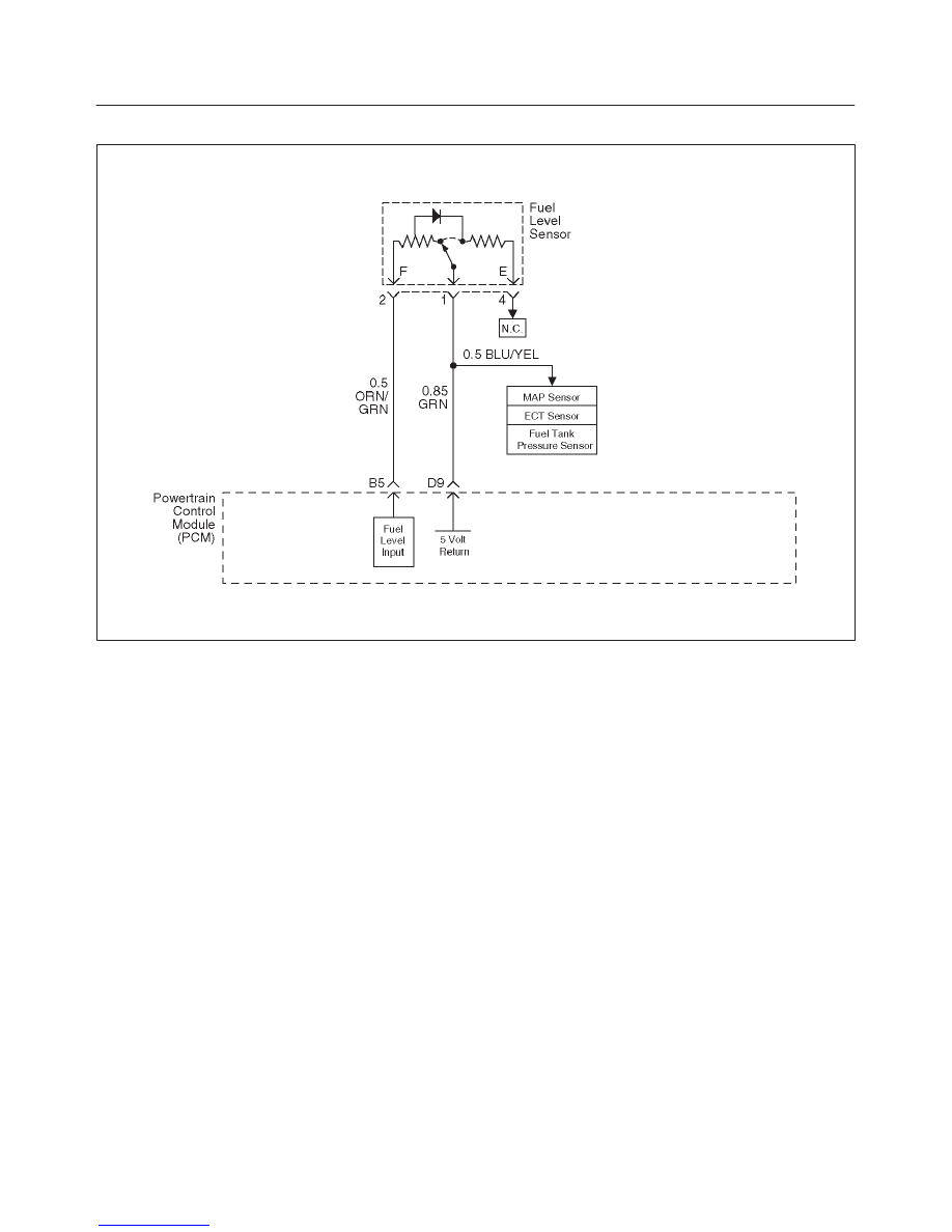
Diagnostic Trouble Code (DTC) P0463 Fuel Level Sensor Circuit–High Voktage
D06RW080
Circuit Description
The fuel level sensor is an important input to powertrain
control module (PCM) for the enhanced evaporative
system diagnostic. Fuel level information is needed for
the PCM to know the volume of fuel in the tank. The fuel
level affects the rate of change in air pressure in the
evaporative system. Several of the enhanced
evaporative system diagnostic sub-tests are dependent
upon correct fuel level information. The diagnostic will not
run when the tank is greater than 85% or less than 15%,
full. Fuel level DTCs should be diagnosed before other
evaporative system DTCs because they can cause other
DTCs to be set.
The sending unit is a float in the fuel tank which moves a
wiper arm across a variable resistor. High fuel level
causes low resistance in the sending unit. This is
recognized by the PCM because the circuit operates at a
corresponding high voltage. When the circuit is
continuously shorted to a voltage source greater than a
specified value, or when the 5 volt signal is shorted to
ground, DTC P0463 is set.
Conditions for Setting the DTC
f
Fuel tank level “slosh test” is completed.
f
Fuel tank level “main test” is completed.
f
Fuel tank level data is valid.
f
Fuel tank level signal is greater than a specified value.
f
There are 100 test failures within a 200-test sample.
Action Taken When the DTC Sets
f
The PCM will not turn the malfunction indicator lamp
(MIL) “ON.”
f
The PCM will store conditions which were present
when the DTC set as Failure Records only. This
information will not be stored as Freeze Frame data.
Conditions for Clearing the DTC
f
The PCM will turn the MIL “OFF” after three
consecutive trips without a fault condition present. A
history DTC will be cleared if no fault conditions have
been detected for 40 warm-up cycles (engine coolant
temperature has risen 4
°
C (40
°
F) from the start-up
ECT, and ECT exceeds 71
°
C (160
°
F) during that
same ignition cycle) or the scan tool clearing function
has been used.
f
DTC P0463 can be cleared by using the scan tool
“Clear Info” function or by disconnecting the PCM
battery feed.
Diagnostic Aids
f
Damaged harness–Inspect the wiring harness for
damage. If the harness appears to be OK, observe the
fuel level display on the scan tool while moving
connectors and wiring harnesses related to the sensor.
A change in the display will indicate the location of the
fault.
Test Description
Number(s) below refer to the step number(s) on the
Diagnostic Chart.

6E2–346
RODEO 6VD1 3.2L ENGINE DRIVEABILITY AND EMISSIONS
2. The ECT and MAP sensors share a ground at PCM
terminal D9.
9. Equates the resistance values at various float
positions to the following fuel gauge readings:
DTC P0463– Fuel Level Sensor Circuit –High Voltage
Step
Action
Value(s)
Yes
No
1
Was the “On-Board Diagnostic (OBD) System Check”
performed?
—
Go to
Step 2
Go to
OBD
System
Check
2
Were any ECT or MAP DTCs set? (ECT and MAP
Sharing Ground with PCM term D9)
—
Go to other
DTC chart
Go to
Step 3
3
1. Disconnected the fuel level sensor harness from its
connector at the fuel tank.
2. Ignition “ON,” engine “OFF.”
3. Using a DVM, measure the voltage between the
sensor harness positive and ground wires.
Is the voltage approximately equal to the specified
value?
5 V
Go to
Step 9
Go to
Step 4
4
With the negative DVM lead connected to ground, use
the positive DVM lead to probe the sensor ground wire
with the harness still disconnected.
Does the DVM indicate a short to a voltage source?
—
Go to
Step 5
Go to
Step 6
5
Repair short to voltage between the sensor and the
PCM.
Is the repair complete?
—
Verify repair
—
6
With the negative DVM lead connected to ground, use
the positive DVM lead to probe the sensor positive wire
with the harness still disconnected.
Does the DVM indicate a voltage greater than the
specified value?
5 V
Go to
Step 5
Go to
Step 7
7
Open circuit between the PCM connector and the fuel
level sensor?
—
Verify repair
Go to
Step 8
8
Replace the PCM.
IMPORTANT: The replacement PCM must be
programmed. Refer to
On-Vehicle Service in
Powertrain Control Module and Sensors for
procedures.
And also refer to latest service bulletin.
Check to see if the Latest software is released or not.
And then Down Load the LATEST PROGRAMMED
SOFTWARE to the replacement PCM.
Is the action complete?
—
Verify repair
—
9
Remove the fuel level sensor and check the following:
f
Does the arm move freely?
f
Are the wire leads shorted together?
f
Do the resistance values match the specification
chart?
Was a problem found?
—
Go to
Step 10
Go to
Step 8
10
Replace the fuel level sensor.
Is the repair complete?
—
Verify repair
—
Нет комментариевНе стесняйтесь поделиться с нами вашим ценным мнением.
Текст