Isuzu Rodeo UE. Manual — part 398
6E2–347
RODEO 6VD1 3.2L ENGINE DRIVEABILITY AND EMISSIONS
Diagnostic Trouble Code (DTC) P0502 VSS Circuit Low Input
D06RX021
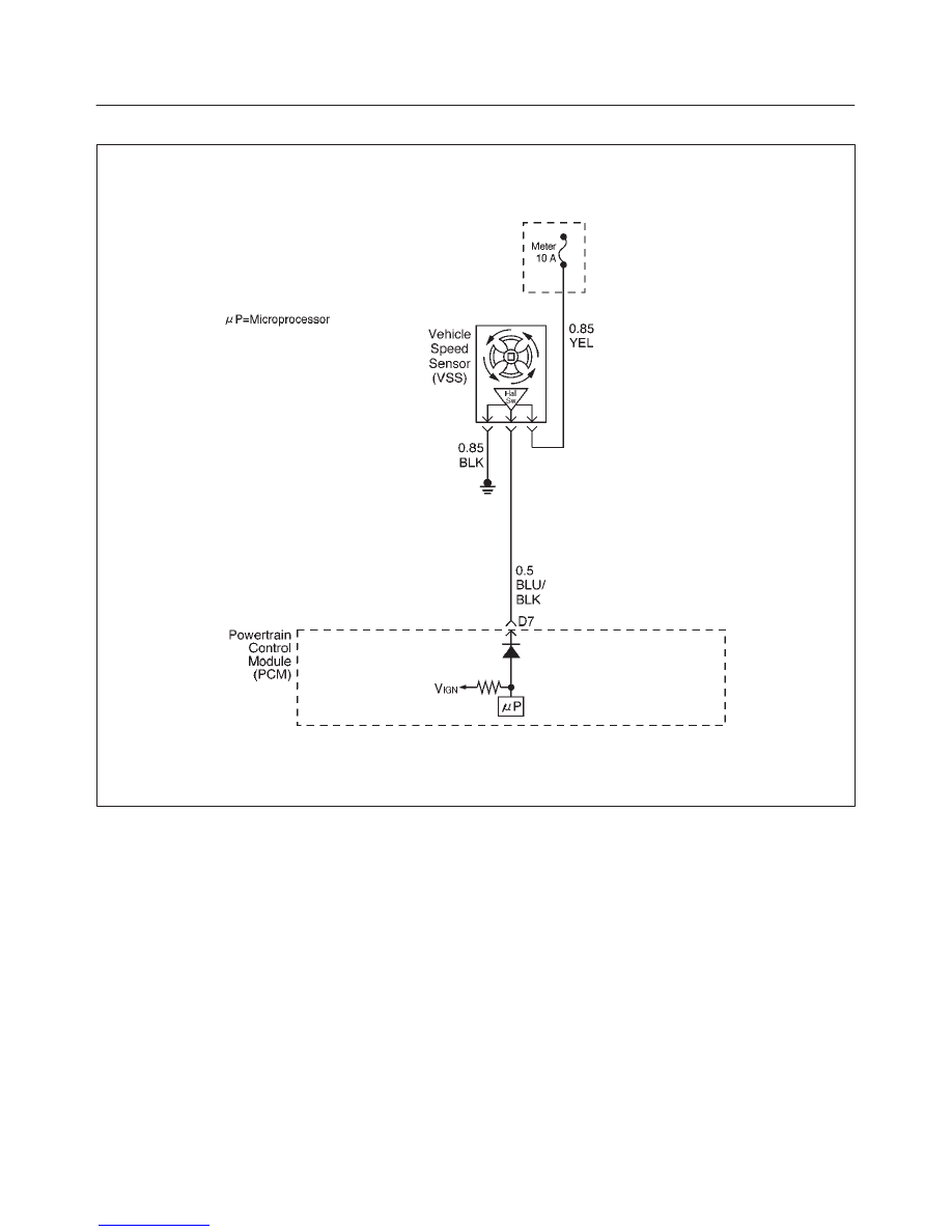
Circuit Description
The vehicle speed sensor has a magnet rotated by the
transmission output shaft. Attached to the sensor is a hall
effect circuit the interacts with the magnetic field treated
by the rotating magnet. A 12-volt operating supply for the
speed sensor hall circuit is supplied from the meter fuse.
The VSS pulses to ground the 9-volt signal sent from the
powertrain control module (PCM) on the reference circuit.
The PCM interprets vehicle speed by the number of
pulses to ground per second on the reference circuit.
Conditions for Setting the DTC
f
Engine is running.
f
Engine coolant temperature is above 60
°
C (140
°
F).
f
Engine speed is between 1800 RPM and 2500 RPM.
f
Throttle angle is between 10% and 40%.
f
Engine load is greater than 50 kPa.
f
MAP sensor indicates greater than 50 kPa manifold
pressure.
f
PCM detects no VSS signal for 12.5 seconds over a
period of 25 seconds.
Action Taken When the DTC Sets
f
The PCM will illuminate the malfunction indicator lamp
(MIL) the first time the fault is detected.
f
The PCM will store conditions which were present
when the DTC was set as Freeze Frame and in the
Failure Records data.
Conditions for Clearing the MIL/DTC
f
The PCM will turn the MIL “OFF” on the third
consecutive trip cycle during which the diagnostic has
been run and the fault condition is no longer present.
f
A history DTC P0502 will clear after 40 consecutive
warm-up cycles have occurred without a fault.
f
DTC P0502 can be cleared by using the Tech 2 “Clear
Info” function or by disconnecting the PCM battery
feed.

6E2–348
RODEO 6VD1 3.2L ENGINE DRIVEABILITY AND EMISSIONS
Test Description
Number(s) below refer to the step number(s) on the
Diagnostic Chart.
9. To avoid backprobing the VSS and possibly
damaging a seal or terminal, the VSS output can be
tested at the point where the transmission harness
connected to the engine harness. The green 16-way
connector is adjacent to a blue 16-way connector,
and it can be easily accessed by removing the air
cleaner assembly. The green 16-way connector is
separated, and battery voltage is applied to the VSS
through the yellow wire at one corner of the
connector. The VSS output can be monitored with a
DVM connected to the blue wire with a black tracer.
The two wires are next to each other in the 16-way
connector . The test connections are made on the
transmission side of the connector, the side that is
not clipped to the body sheetmetal.
14. The speedometer-to-PCM VSS signal wire is
spliced to a wire leading to the cruise control
module. If a short to ground or voltage is found
between the PCM and speedometer, it could be
located between the splice and the cruise control
module.
DTC P0502 –VSS Circuit Low Input
Step
Action
Value(s)
Yes
No
1
Was the “On-Board Diagnostic (OBD) System Check”
performed?
—
Go to
Step 2
Go to
OBD
System
Check
2
Does the speedometer work?
—
Go to
Step 10
Go to
Step 3
3
1. Disconnect the VSS connector.
2. Ignition “ON.”
3. Using a test light to battery +, probe the connector
ground wire.
Did the light illuminate?
—
Go to
Step 5
Go to
Step 4
4
Repair the sensor ground.
Is the action complete?
—
Verify repair
—
5
1. Ignition “ON,” sensor disconnected.
2. Using a DVM, measure at the VSS connector
between ground and voltage supply.
Was the measurement near the specified value?
Battery
voltage
Go to
Step 7
Go to
Step 6
6
Repair the open or short to ground which may have
blown the meter fuse.
Is the action complete?
—
Verify repair
—
7
1. Ignition “ON,” VSS disconnected.
2. Using a DVM, measure at the VSS connector
between ground and the blue/black wire from the
speedometer.
Was the measurement near the specified value?
7.5-8 V
Go to
Step 9
Go to
Step 8
8
Check for an open or short circuit between the
speedometer and the VSS.
Was an open or short circuit located?
—
Verify repair
Go to
Step 9
9
Replace the speedometer.
Is the action complete?
—
Verify repair
—

6E2–349
RODEO 6VD1 3.2L ENGINE DRIVEABILITY AND EMISSIONS
DTC P0502 –VSS Circuit Low Input
(Cont'd)
Step
No
Yes
Value(s)
Action
10
1. Ignition “OFF.”
2. Disconnect the MAF sensor. The connector
attaches the VSS wires from the transmission
harness to the left-side engine harness.
3. Disconnect the green 16-way connector.
4. Select a terminal adapter from kit J 35616 that can
be used with a jumper to supply B+ to the yellow
(transmission side of the connector). There are 2
yellow wires at that connector, but the correct one is
in the corner position.
5. Use another terminal adapter to attach a voltmeter
to the blue wire with a black tracer (next to the wire in
the previous step.)
6. At the transmission side of the green 16-way
connector, locate the black wire next to the VSS
yellow ign+ wire. The black wire is the VSS ground
wire. Use a terminal adapter to attach a jumper to
ground to the black VSS ground wire at the
transmission side of the connector.
7. Raise the rear wheels off the ground with
transmission in neutral.
Does the DVM toggle back and forth between 0.6 V and
10 V as the wheels (and driveshaft) are rotated?
—
Go to
Step 12
Go to
Step 11
11
Replace the VSS.
Is the action complete?
—
Verify repair
—
12
Check for an open or short between the PCM and the
speedometer.
Was a problem found?
—
Verify repair
Go to
Step 13
13
Replace the PCM.
IMPORTANT: The replacement PCM must be
programmed. Refer to
On-Vehicle Service in
Powertrain Control Module and Sensors for
procedures.
And also refer to latest Service Bulletin.
Check to see if the Latest software is released or not.
And then Down Load the LATEST PROGRAMMED
SOFTWARE to the replacement PCM.
Is the action complete?
—
Verify repair
—
6E2–350
RODEO 6VD1 3.2L ENGINE DRIVEABILITY AND EMISSIONS
Diagnostic Trouble Code (DTC) P0506 Idle Air Control System Low RPM
T321115
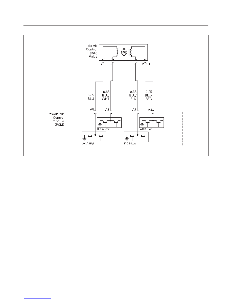
Circuit Description
The powertrain control module (PCM) controls engine
idle speed by adjusting the position of the idle air control
(IAC) motor pintle. The IAC is a bi-directional stepper
motor driven by two coils. The PCM applies current to the
IAC coils in steps (counts) to extend the IAC pintle into a
passage in the throttle body to decrease air flow. The
PCM reverses the current to retract the pintle, increasing
air flow. This method allows highly accurate control of idle
speed and quick response to changes in engine load. If
the PCM detects a condition where too low of an idle
speed is present and the PCM is unable to adjust idle
speed by increasing the IAC counts, DTC P0506 will set,
indicating a problem with the idle control system.
Conditions for Setting the DTC
f
No Tech 2 test is being run.
f
No TPS, VSS, ECT, EGR, MAF, MAP, IAT, misfire, low
voltage, fuel system, canister purge, injector control, or
ignition control DTCs are set.
f
Barometric pressure is above 75 kPa.
f
Canister purge duty cycle is above 10%.
f
Engine running time is more than 125 seconds.
f
Vehicle speed is less than 1 mph.
f
Engine coolant temperature (ECT) is above 50
°
C.
f
Ignition voltage is between 9.5 volts and 16.7 volts.
f
The throttle is closed.
f
EVAP purge duty cycle more than 10%.
f
All conditions are met for 10 seconds.
f
Engine speed is more than 100-200 RPM lower than
desired idle based upon coolant temperature.
Action Taken When the DTC Sets
f
The PCM will illuminate the malfunction indicator lamp
(MIL) after the second consecutive trip in which the
fault is detected.
f
The PCM will store conditions which were present
when the DTC was set as Freeze Frame and in the
Failure Records data.
Conditions for Clearing the MIL/DTC
f
DTC P0506 can be cleared by using the Tech 2 “Clear
Info” function or by disconnecting the PCM battery
feed.
Diagnostic Aids
Check for the following conditions:
f
Poor connection at PCM or IAC motor – Inspect
harness connectors for backed-out terminals,
improper mating, broken locks, improperly formed or
damaged terminals, and poor terminal-to-wire
connection.
f
Damaged harness – Inspect the wiring harness for
damage.
f
Restricted air intake system – Check for a possible
collapsed air intake duct, restricted air filter element, or
foreign objects blocking the air intake system.
f
Throttle body – Check for objects blocking the IAC
passage or throttle bore, excessive deposits in the IAC
Нет комментариевНе стесняйтесь поделиться с нами вашим ценным мнением.
Текст