Isuzu Rodeo UE. Manual — part 128
6A–1
ENGINE MECHANICAL (X22SE 2.2L)
RODEO
ENGINE
CONTENTS
Engine Mechanical
6A–1
. . . . . . . . . . . . . . . . . . . . . .
Engine Cooling
6B–1
. . . . . . . . . . . . . . . . . . . . . . . . .
Engine Fuel
6C–1
. . . . . . . . . . . . . . . . . . . . . . . . . . . .
Engine Electrical
6D1–1
. . . . . . . . . . . . . . . . . . . . . . . .
Ignition System
6D2–1
. . . . . . . . . . . . . . . . . . . . . . . . .
Starting and Charging System
6D3–1
. . . . . . . . . . . .
Driveability and Emissions
6E1–1
. . . . . . . . . . . . . . . .
Engine Exhaust
6F–1
. . . . . . . . . . . . . . . . . . . . . . . . .
Engine Lubrication
6G–1
. . . . . . . . . . . . . . . . . . . . . .
Engine Speed Control System
6H–1
. . . . . . . . . . . .
Induction
6J–1
. . . . . . . . . . . . . . . . . . . . . . . . . . . . . . .
ENGINE MECHANICAL (X22SE 2.2L)
CONTENTS
Service Precaution
6A–2
. . . . . . . . . . . . . . . . . . . . . .
General Description
6A–2
. . . . . . . . . . . . . . . . . . . . .
Engine Diagnosis
6A–3
. . . . . . . . . . . . . . . . . . . . . . .
Cylinder Head Cover
6A–16
. . . . . . . . . . . . . . . . . . . .
Removal
6A–16
. . . . . . . . . . . . . . . . . . . . . . . . . . . . .
Installation
6A–17
. . . . . . . . . . . . . . . . . . . . . . . . . . . .
Exhaust Manifold
6A–18
. . . . . . . . . . . . . . . . . . . . . . . .
Removal
6A–18
. . . . . . . . . . . . . . . . . . . . . . . . . . . . .
Installation
6A–18
. . . . . . . . . . . . . . . . . . . . . . . . . . . .
Crankshaft Pulley
6A–19
. . . . . . . . . . . . . . . . . . . . . . .
Removal
6A–19
. . . . . . . . . . . . . . . . . . . . . . . . . . . . .
Installation
6A–19
. . . . . . . . . . . . . . . . . . . . . . . . . . . .
Intake Manifold
6A–20
. . . . . . . . . . . . . . . . . . . . . . . . .
Removal
6A–20
. . . . . . . . . . . . . . . . . . . . . . . . . . . . .
Installation
6A–21
. . . . . . . . . . . . . . . . . . . . . . . . . . . .
Cylinder Head Assembly
6A–22
. . . . . . . . . . . . . . . . .
Removal
6A–22
. . . . . . . . . . . . . . . . . . . . . . . . . . . . .
Installation
6A–24
. . . . . . . . . . . . . . . . . . . . . . . . . . . .
Timing Belt
6A–28
. . . . . . . . . . . . . . . . . . . . . . . . . . . . .
Removal
6A–28
. . . . . . . . . . . . . . . . . . . . . . . . . . . . .
Installation
6A–29
. . . . . . . . . . . . . . . . . . . . . . . . . . . .
Camshaft
6A–32
. . . . . . . . . . . . . . . . . . . . . . . . . . . . . .
Removal
6A–32
. . . . . . . . . . . . . . . . . . . . . . . . . . . . .
Installation
6A–33
. . . . . . . . . . . . . . . . . . . . . . . . . . . .
Engine Assembly
6A–35
. . . . . . . . . . . . . . . . . . . . . . . .
Removal
6A–36
. . . . . . . . . . . . . . . . . . . . . . . . . . . . .
Installation
6A–37
. . . . . . . . . . . . . . . . . . . . . . . . . . . .
Cylinder Head
6A–39
. . . . . . . . . . . . . . . . . . . . . . . . . .
Cylinder Head and Associated Parts
6A–39
. . . . .
Disassembly
6A–39
. . . . . . . . . . . . . . . . . . . . . . . . . .
Inspection and Repair
6A–40
. . . . . . . . . . . . . . . . . .
Reassembly
6A–41
. . . . . . . . . . . . . . . . . . . . . . . . . .
Valve Spring, Valve, Valve Guide
6A–42
. . . . . . . . . .
Valve Spring, Valve, Valve Guide and
Associated Parts
6A–42
. . . . . . . . . . . . . . . . . . . . . .
Disassembly
6A–42
. . . . . . . . . . . . . . . . . . . . . . . . . .
Inspection and Repair
6A–43
. . . . . . . . . . . . . . . . . .
Reassembly
6A–44
. . . . . . . . . . . . . . . . . . . . . . . . . .
Camshaft
6A–45
. . . . . . . . . . . . . . . . . . . . . . . . . . . . . .
Camshaft and Associated Parts
6A–45
. . . . . . . . .
Disassembly
6A–45
. . . . . . . . . . . . . . . . . . . . . . . . . .
Reassembly
6A–46
. . . . . . . . . . . . . . . . . . . . . . . . . .
Crankshaft
6A–47
. . . . . . . . . . . . . . . . . . . . . . . . . . . . .
Crankshaft and Associated Parts
6A–47
. . . . . . . .
Disassembly
6A–47
. . . . . . . . . . . . . . . . . . . . . . . . . .
Inspection and Repair
6A–48
. . . . . . . . . . . . . . . . . .
Inspection and Repair
6A–49
. . . . . . . . . . . . . . . . . .
Reassembly
6A–50
. . . . . . . . . . . . . . . . . . . . . . . . . .
Piston and Connecting Rod
6A–53
. . . . . . . . . . . . . . .
Piston, Connecting Rod and Associate
Parts
6A–53
. . . . . . . . . . . . . . . . . . . . . . . . . . . . . . . .
Disassembly
6A–53
. . . . . . . . . . . . . . . . . . . . . . . . . .
Inspection and Repair
6A–54
. . . . . . . . . . . . . . . . . .
Reassembly
6A–56
. . . . . . . . . . . . . . . . . . . . . . . . . .
Cylinder Block
6A–57
. . . . . . . . . . . . . . . . . . . . . . . . . .
Cylinder Block and Associated Parts
6A–57
. . . . .
Disassembly
6A–58
. . . . . . . . . . . . . . . . . . . . . . . . . .
Inspection and Repair
6A–58
. . . . . . . . . . . . . . . . . .
Reassembly
6A–59
. . . . . . . . . . . . . . . . . . . . . . . . . .
Cylinder Head Cover
6A–60
. . . . . . . . . . . . . . . . . . . .
Cylinder Head Cover and Associated parts
6A–60
Removal
6A–61
. . . . . . . . . . . . . . . . . . . . . . . . . . . . .
Installation
6A–61
. . . . . . . . . . . . . . . . . . . . . . . . . . . .
Balance Unit Assembly
6A–63
. . . . . . . . . . . . . . . . . .
Balance Unit Assembly Associated Parts
6A–63
.
Disassembly
6A–64
. . . . . . . . . . . . . . . . . . . . . . . . . .
Adjustment
6A–64
. . . . . . . . . . . . . . . . . . . . . . . . . . .
Reassembly
6A–66
. . . . . . . . . . . . . . . . . . . . . . . . . .
Main Data and Specifications
6A–68
. . . . . . . . . . . . .
Special Tools
6A–73
. . . . . . . . . . . . . . . . . . . . . . . . . . .
6A–2
ENGINE MECHANICAL (X22SE 2.2L)
Service Precaution
WARNING: THIS VEHICLE HAS A SUPPLEMENTAL
RESTRAINT SYSTEM (SRS). REFER TO THE SRS
COMPONENT AND WIRING LOCATION VIEW IN
ORDER TO DETERMINE WHETHER YOU ARE
PERFORMING SERVICE ON OR NEAR THE SRS
COMPONENTS OR THE SRS WIRING. WHEN YOU
ARE PERFORMING SERVICE ON OR NEAR THE SRS
COMPONENTS OR THE SRS WIRING, REFER TO
THE SRS SERVICE INFORMATION. FAILURE TO
FOLLOW WARNINGS COULD RESULT IN POSSIBLE
AIR BAG DEPLOYMENT, PERSONAL INJURY, OR
OTHERWISE UNNEEDED SRS SYSTEM REPAIRS.
CAUTION: Always use the correct fastener in the
proper location. When you replace a fastener, use
ONLY the exact part number for that application.
ISUZU will call out those fasteners that require a
replacement after removal. ISUZU will also call out
the fasteners that require thread lockers or thread
sealant. UNLESS OTHERWISE SPECIFIED, do not
use supplemental coatings (Paints, greases, or other
corrosion inhibitors) on threaded fasteners or
fastener joint interfaces. Generally, such coatings
adversely affect the fastener torque and the joint
clamping force, and may damage the fastener. When
you install fasteners, use the correct tightening
sequence and specifications. Following these
instructions can help you avoid damage to parts and
systems.
General Description
Engine Cleanliness And Care
An automobile engine is a combination of many
machined, honed, polished and lapped surfaces with
tolerances that are measured in the thousandths of a
millimeter (ten thousandths of an inch). Accordingly,
when any internal engine parts are serviced, care and
cleanliness are important. Throughout this section, it
should be understood that proper cleaning and protection
of machined surfaces and friction areas is part of the
repair procedure. This is considered standard shop
practice even if not specifically stated.
f
A liberal coating of engine oil should be applied to all
friction areas during assembly to protect and lubricate
the surfaces on initial operation.
f
Whenever valve train components, pistons, piston
rings, connecting rods, rod bearings, and crankshaft
journal bearings are removed for service, they should
be retained in order.
f
At the time of installation, they should be installed in
the same locations and with the same mating
surfaces as when removed.
f
Battery cables should be disconnected before any
major work is performed on the engine. Failure to
disconnect cables may result in damage to wire
harness or other electrical parts.
f
The four cylinders of this engine are identified by
numbers; cylinders 1, 2, 3 and 4, as counted from
crankshaft pulley.
General Information on Engine Service
The following information on engine service should be
noted carefully, as it is important in preventing damage
and contributing to reliable engine performance:
f
When raising or supporting the engine for any reason,
do not use a jack under the oil pan. Due to the small
clearance between the oil pan and the oil pump
strainer, jacking against the oil pan may cause
damage to the oil pick up unit.
f
The 12–volt electrical system is capable of damaging
circuits. When performing any work where electrical
terminals could possibly be grounded, the ground
cable of the battery should be disconnected at the
battery.
f
Any time the intake air duct or air cleaner is removed,
the intake opening should be covered. This will
protect against accidental entrance of foreign
material into the cylinder which could cause extensive
damage when the engine is started.
Cylinder Block
The cylinder block is made of cast iron. The crankshaft is
supported by five bearings. The bearing cap is made of
nodular cast iron.
Cylinder Head
The cylinder head is made of aluminum alloy casting with
a spark plug in the center.
Valve Train
Valve system is direct–acting invertered bucket tappet.
The valves clearance adjustment are hydraulic.
Hydraulic valve lash adjustment, no adjustment
necessary.
Intake Manifold
The intake manifold is made of aluminum alloy.
Exhaust Manifold
The exhaust manifold is made of high Si–Mo nodular iron.
Pistons and Connecting Rods
Aluminum pistons are used after selecting the grade that
meets the cylinder bore diameter. Each piston has two
compression rings and one oil ring. The piston pin is made
of case–harded steel. The connecting rods are made of
cast iron. The connecting rod bearings are made of steel
backed with babbitt metal.
Crankshaft and Bearings
The crankshaft is made of nodular cast iron. Pins and
journals are graded for correct size selection for their
bearing.
Balance Shaft
Type is lanchester (twin counter–rotating shafts). The
balance shafts are made of cast iron and gears are hard
faced. The housing is made of cast iron. Backlash
adjustment method is shim–balancer housing to block
(selective fit).
6A–3
ENGINE MECHANICAL (X22SE 2.2L)
Engine Diagnosis
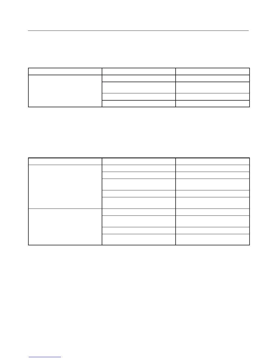
Hard Starting
1. Starting Motor Does Not Turn Over
Trouble Shooting Procedure
Turn on headlights and starter switch.
Condition
Possible cause
Correction
Headlights go out or dim
considerably
Battery run down or under charged
Recharge or replace battery
considerably
Terminals poorly connected
Clean battery posts and terminals
and connect properly
Starting motor coil circuit shorted
Overhaul or replace
Starting motor defective
Overhaul or replace
2. Ignition Trouble — Starting Motor Turns Over But Engine Does Not Start
Spark Test
Disconnect a high tension cable from any spark plug.
Connect the spark plug tester J–26792 (ST–125), crank
the engine, and check if a spark is generated in the spark
plug tester. Before cranking the engine, make sure that
the spark plug tester is properly grounded. To avoid elec-
trical shock, do not touch the high tension cable while the
engine is running.
Condition
Possible cause
Correction
Spark jumps across gap
Spark plug defective
Clean, adjust spark gap or replace
Ignition timing incorrect
Refer to Ignition System
Fuel not reaching fuel injector(s) or
engine
Refer to item 3 (Trouble in fuel
system)
Valve timing incorrect
Adjust
Engine lacks compression
Refer to item 4 (Engine lacks
compression)
No sparking takes place
Ignition coil disconnected or broken
Connect properly or replace
Electronic Ignition System with
module
Replace
Poor connections in engine harness
Correct
Powertrain Control Module cable
disconnected or defective
Correct or replace
6A–4
ENGINE MECHANICAL (X22SE 2.2L)
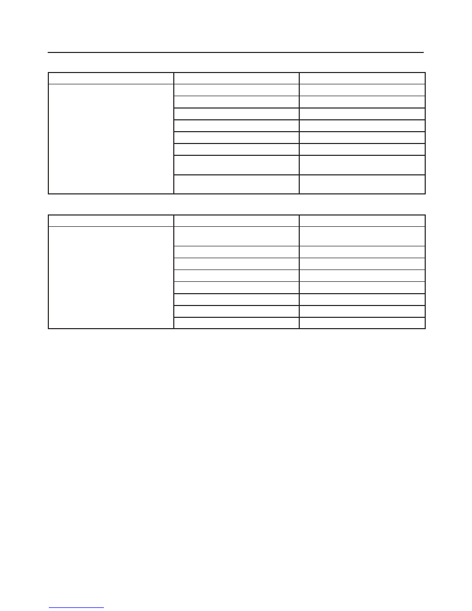
3. Trouble In Fuel System
Condition
Possible cause
Correction
Starting motor turns over and spark
occurs but engine does not start
Fuel tank empty
Fill
occurs but engine does not start.
Water in fuel system
Clean
Fuel filter clogged
Replace filter
Fuel pipe clogged
Clean or replace
Fuel pump defective
Replace
Fuel pump circuit open
Correct or replace
Evaporative Emission Control
System circuit clogged
Correct or replace
Multiport Fuel Injection System faulty
Refer to “Electronic Fuel Injection”
section
4. Engine Lacks Compression
Condition
Possible cause
Correction
Engine lacks compression
Spark plug loosely fitted or spark
plug gasket defective
Tighten to specified torque or replace
gasket
Valve timing incorrect
Adjust
Cylinder head gasket defective
Replace gasket
Valve incorrectly seated
Lap valve
Valve stem seized
Replace valve and valve guide
Valve spring weakened
Replace
Cylinder or piston rings worn
Overhaul engine
Piston ring seized
Overhaul engine.
Engine Compression Test Procedure
1. Start and run the engine until the engine reaches
normal operating temperature.
2. Turn the engine off.
3. Remove all the spark plugs.
4. Remove ignition coil fuse (15A) and disable the
ignition system.
5. Remove the fuel pump relay from the relay and fuse
box.
6. Engage the starter and check that the cranking speed
is approximately 300 rpm.
7. Install cylinder compression gauge into spark plug
hole.
8. With the throttle valve opened fully, keep the starter
engaged until the compression gage needle reaches
the maximum level. Note the reading.
9. Repeat the test with each cylinder.
The pressure difference between the individual
cylinders should not exceed 100 kPa (14.5 psi).
Нет комментариевНе стесняйтесь поделиться с нами вашим ценным мнением.
Текст