Isuzu Rodeo UE. Manual — part 486

TRANSMISSION CONTROL SYSTEM (4L30–E)
7A1–63
DTC P0748 Pressure Control Solenoid (PCS) (Force Motor) Circuit Electrical
Step
Action
Yes
No
1
Were you sent here from the “Powertrain On–Board Diagnostic
(OBD) System Check”?
Go to Step 2
Go to OBD
System Check
Refer to
Driveability and
Emission in
Engine section
2
1. Install the scan tool.
2. With the engine “off”, turn the ignition switch “on”.
NOTE: Before clearing DTC(s), use the scan tool to record “Failure
Records” for reference, as data will be lost when the “Clear Info”
function is used.
3. Record the DTC “Failure Records”.
4. While the engine is operating, put the transmission in Park.
5. Using the scan tool, apply 0.1 amp through 1.0 amp while
observing “PC Ref. Current” and “PC Act. Current”.
Is the “PC Act. Current” reading always within 0.16 amp?
Go to Diagnostic
Aids
Go to Step 3
3
1. Turn the ignition “off”.
2. Disconnect the transmission 5–way connector M–6.
3. Using the J39200 DVOM, measure the resistance between
terminals M6–2(B) and M6–1(E).
Is the resistance within 3–7 ohms?
Go to Step 7
Go to Step 4
4
1. Remove the transmission oil pan. Refer to Solenoid (Adapter
Case Valve Body) in Automatic Transmission (4L30–E)
section.
2. Disconnect the internal wiring harness at the PCS.
3. Measure the resistance of the PCS.
Is the resistance within 3–7 ohms?
Go to Step 6
Go to Step 5
5
Replace the PCS.
Is the replacement complete?
Go to Step 10
—
6
Repair the internal wiring harness for an open.
Is the repair complete?
Go to Step 10
—
7
Inspect/repair circuits C3–E4, M6–2(B), C3–E3, M6–1(E).
Was a problem found?
Go to Step 10
Go to Step 8
8
Inspect/repair circuits C3–E4, M6–2(B), C3–E3, M6–1(E) for a
short to ground or poor connections.
Was a problem found?
Go to Step 10
Go to Step 9
9
Replace the PCM. Refer to Powertrain Control Module (PCM) in
Automatic Transmission (4L30–E) section.
Is the replacement complete?
Go to Step 10
—
10
1. After the repair is complete, use the scan tool to select “DTC”,
then “Clear Info” function and ensure the following conditions
are met:
The PCS duty cycle is not at its electrical high or low limit.
2. Review the scan tool “DTC Info”.
Has the last test failed or is the current DTC displayed?
Begin diagnosis
again
Go to Step 1
Repair verified
Exit DTC table
7A1–64 TRANSMISSION CONTROL SYSTEM (4L30–E)
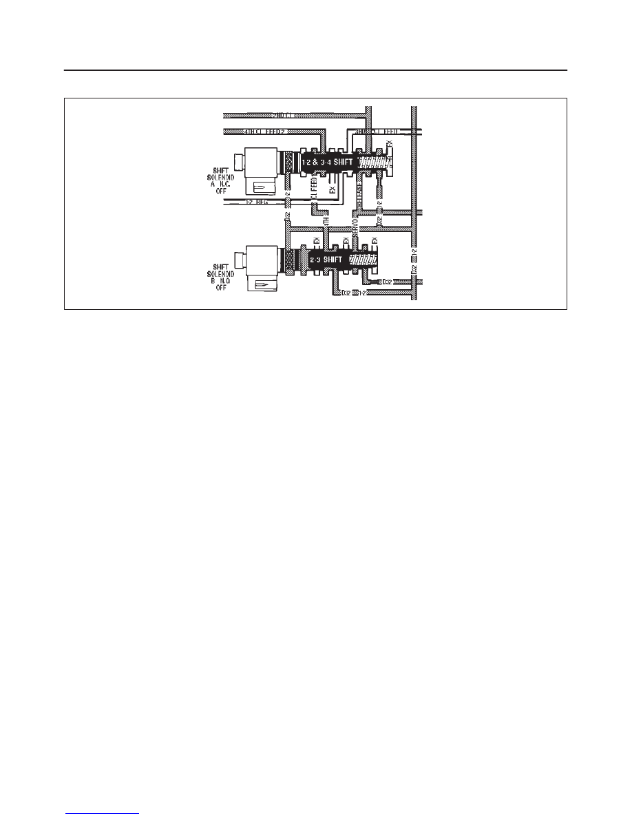
DTC P0751 Shift Solenoid A Performance Without Input Speed
D07RT011
Circuit Description
The shift solenoid A is used to control fluid flow acting on
the 1–2 and 3–4 shift valves. The solenoid is a normally
close exhaust valve that is used with the shift solenoid B
to allow four different shifting combinations.
The DTC detects a 2–3 only or a 1–4 only shift pattern
depending on the state of the mechanical failure. This is a
type “B” DTC.
Conditions For Setting The DTC
f
No TP DTCs P0122 or P0123.
f
No OSS DTCs P0722 or P0723.
f
No TCC solenoid DTC P0742, P1860.
f
No shift solenoid A DTC P0753.
f
No shift solenoid B DTC P0758.
f
Gear range is D4.
f
Vehicle speed is greater than 10 km/h (6.25 mph).
f
Transmission temperature is between 20
°
and 125
°
C
(68
°
and 257
°
F).
All the above conditions have been met and the
combination of conditions 1, 2, 3, and 4 or 1, 2, 3, and 5
occur two consecutive times.
Condition 1:
f
Commanded 1–2 shift.
f
TP angle is between 10 and 60%.
f
TP angle is constant within +/–3%.
f
Vehicle speed is between 18 and 50 km/h (11 and 31
mph).
f
Within 2.2 seconds, the engine speed in 2nd gear
must be 100 rpm greater than the last speed in 1st
gear.
Condition 2:
f
Commanded 2–3 shift.
f
TP angle is between 13 and 60%.
f
TP angle is constant within +/–5%.
f
Vehicle speed is between 30 and 88 km/h (20 and 45
mph).
f
Within 2 seconds, the engine speed in 3rd gear must
be 64 rpm less than the last speed in 2nd gear.
Condition 3:
f
Commanded 3–4 shift.
f
TP angle is between 7 and 60%.
f
TP angle is constant within +/–5%.
f
Vehicle speed is between 40 and 140 km/h (25 and 87
mph).
f
Within 0.7 seconds, the engine speed in 4th gear
must be –60 rpm greater than the last speed in 3rd
gear.
Condition 4:
f
Commanded 4th gear.
f
TCC is “on”.
f
TP angle is between 13 and 60%.
f
Speed ratio is between 0.85 and 1.2 (speed ratio is
engine speed
÷
output speed).
f
TCC slip speed is between 100 and 2000 rpm for 3
seconds.
Condition 5:
f
Commanded 4th gear.
f
TCC is “on”.
f
TP angle is between 13 and 60%.
f
Speed ratio is between 0.5 and 0.85.
f
TCC slip speed is between –50 and 500 rpm for 3
seconds.
Action Taken When the DTC Sets
f
Maximum line pressure.

TRANSMISSION CONTROL SYSTEM (4L30–E)
7A1–65
f
The PCM will illuminate the Malfunction Indicator
Lamp (MIL) and CHECK TRANS Lamp.
Conditions For Clearing The The MIL/DTC
f
The PCM will turn off the MIL and CHECK TRANS
Lamp after three consecutive ignition cycles without a
failure reported.
f
The DTC can be cleared from the PCM history by
using a scan tool.
f
The DTC will be cleared from history when the vehicle
has achieved 40 warmup cycles without a failure
reported.
f
The PCM will cancel the DTC default actions when
the fault no longer exists and the ignition is cycled “off”
long enough to power down the PCM.
Diagnostic Aids
f
Verify that the transmission meets the specifications
in the 4L30–E shift speed chart.
f
Other internal transmission failures may cause more
than one shift to occur.
f
A shift solenoid A performance problem could set a
shift solenoid B DTC P0756 or a transmission
component slipping DTC P1870.
Test Description
The numbers below refer to the step numbers on the
diagnostic chart:
2. This test checks the function of the range switch
(mode switch).
3. This test checks that the scan tool commanded all
shifts, all shifts solenoids responded correctly, but
all the shifts did not occur.
DTC P0751 Shift Solenoid A Performance Without Input Speed
Step
Action
Yes
No
1
Were you sent here from the “Powertrain On–Board Diagnostic
(OBD) System Check”?
Go to Step 2
Go to OBD
System Check
Refer to
Driveability and
Emission in
Engine section
2
1. Install the scan tool.
2. With the engine “off”, turn the ignition switch “on”.
NOTE: Before clearing DTC(s), use the scan tool to record “Freeze
Frame” and “Failure Records” for reference, as data will be lost
when the “Clear Info” function is used.
3. Record the DTC “Freeze Frame” and “Failure Records”.
4. With the engine operating, apply the brake pedal and select
each transmission range D1, D2, D3, D4, N, R, and P.
Does each selected transmission range match the “TR Switch” on
the scan tool?
Go to Step 3
Go to“Range
Switch Logic
Table”
3
1. While the engine is operating, raise the drive wheels.
2. With the transmission in D4 range, use the scan tool to
command 1st, 2nd and 3rd, and 4th gears while accelerating
the vehicle.
Was a 2–3 or 1–4 only shift pattern detected? (Road testing the
vehicle may be necessary).
Go to Step 4
Go to Diagnostic
Aids
4
Check the shift solenoid/hydraulic circuit for:
f
One or both of the shift solenoids for an internal malfunction.
f
Contamination or sediment in one or both of the shift
solenoids.
f
Damaged seals on one or both of the shift solenoids.
Refer to Solenoid (Main Case Valve Body) in Automatic
Transmission (4L30–E) section.
Was a problem found and corrected?
Go to Step 5
Go to Diagnostic
Aids
5
1. After the repair is complete, use the scan tool to select “DTC”,
then “Clear Info” function and road test the vehicle.
2. Review the scan tool “DTC Info”.
Has the last test failed or is the current DTC displayed?
Begin diagnosis
again
Go to Step 1
Repair verified
Exit DTC table
7A1–66 TRANSMISSION CONTROL SYSTEM (4L30–E)
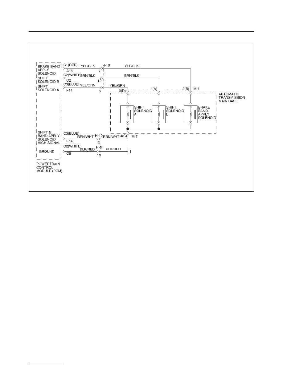
DTC P0753 Shift Solenoid A Electrical
D07RW014
Circuit Description
f
The shift solenoid A is a simple on/off solenoid
located in the main case valve body. The solenoid is
the normally closed type. In second or third gear the
Powertrain Control Module (PCM) energizes the
solenoid to open a fluid inlet port. When the port is
open, fluid pressure actuates the shift valve.
f
The solenoid is activated by a current. This current is
produced by applying a voltage to one side (the High
side) and a ground to the other side (Low side).
f
The High Side Driver (HSD) is a circuit of the PCM
that acts as a switch between the solenoids and the
supply voltage. The High side of the solenoid is
permanently supplied with voltage, except in
BACKUP MODE or when ignition is off the HSD is
turned off.
This DTC detects a continuous open or short to ground in
the shift solenoid A circuit or the shift solenoid A. This is a
type “B” DTC.
Conditions For Setting The DTC
f
Ignition is “on”, Engine “run”.
f
Battery voltage is between 10 and 16 volts.
f
The PCM commands the solenoid “on” and the
voltage remains high (B+), or the PCM commands
the solenoid “off” and the voltage remains low (zero
volts).
f
All conditions met for 0.33 seconds.
Action Taken When The DTC Sets
f
Maximum line pressure.
f
Immediate landing to 4th gear.
f
Inhibit TCC engagement.
f
The PCM will illuminate the Malfunction Indicator
Lamp (MIL) and CHECK TRANS Lamp.
Conditions For Clearing The MIL/DTC
f
The PCM will turn off the MIL and CHECK TRANS
Lamp after three consecutive ignition cycles without a
failure reported.
f
The DTC can be cleared from the PCM history by
using a scan tool.
f
The DTC will be cleared from history when the vehicle
has achieved 40 warmup cycles without a failure
reported.
f
The PCM will cancel the DTC default actions when
the fault no longer exists and the ignition is cycled “off”
long enough to power down the PCM.
Diagnostic Aids
f
Inspect the wiring for poor electrical connection at the
PCM and at the transmission 16–way connector.
Look for possible bent, backed out, deformed or
damaged terminals. Check for weak terminal tension
as well. Also check for a chafed wire that could short
to bare metal or other wiring. Inspect for a broken wire
inside the insulation.
Нет комментариевНе стесняйтесь поделиться с нами вашим ценным мнением.
Текст