Isuzu Rodeo UE. Manual — part 7
0B–11
MAINTENANCE AND LUBRICATION
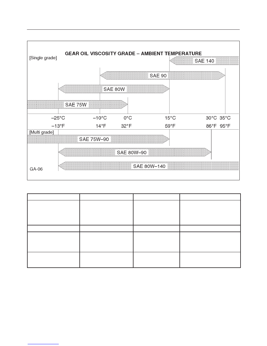
Oil Viscosty Chart for Rear Axle
B00RW004
Recommended Liquid Gasket
Type
Brand Name
Manufacturer
Remarks
RTV*
Silicon Base
Three Bond 1207B
Three Bond 1207C
Three Bond 1215
Three Bond 1280
Three Bond 1281
Three Bond
Three Bond
Three Bond
Three Bond
Three Bond
For Engine Repairs
For Axle Case
Repairs T/M
Repairs T/M
Water Base
Three Bond 1141E
Three Bond
For Engine Repairs
Solvent
Three Bond 1104
Belco Bond 4
Belco Bond 401
Belco Bond 402
Three Bond
Isuzu
Isuzu
Isuzu
For Engine Repairs
Anaerobic
LOCTITE 515
LOCTITE 518
LOCTITE 17430
Loctite
Loctite
Loctite
All
* RTV: Room Temperature Vulcanizer
NOTE:
1. It is very important that the liquid gaskets listed above
or their exact equivalent be used on the vehicle.
2. Be careful to use the specified amount of liquid
gasket.
Follow the manufacturer’s instructions at all times.
3. Be absolutely sure to remove all lubricants and
moisture from the connecting surfaces before
applying the liquid gasket.
The connecting surfaces must be perfectly dry.
4. Do not apply LOCTITE 17430, LOCTITE 515 and
LOCTITE 518 between two metal surfaces having a
clearance of greater than 0.25 mm (0.01 in). Poor
adhesion will result.
0B–12
MAINTENANCE AND LUBRICATION
Recommended Thread Locking
Agents
LOCTITE Type
LOCTITE Color
LOCTITE 242
Blue
LOCTITE 262
Red
LOCTITE 271
Red
Application Steps
1. Completely remove all lubricant and moisture from
the bolts and the female-threaded surfaces of the
parts to be joined.
The surfaces must be perfectly dry.
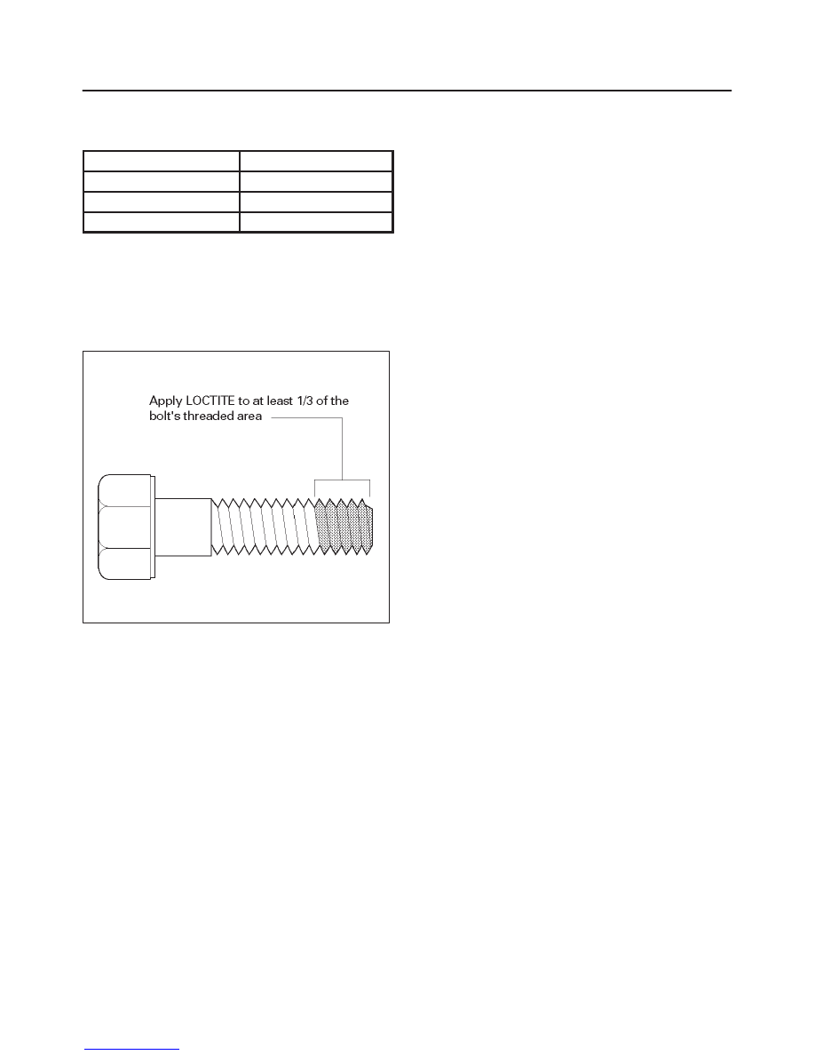
2. Apply LOCTITE to the bolts.
F00RW014
3. Tighten the bolts to the specified torque.
After tightening, be sure to keep the bolts free from
vibration and torque for at least an hour until
LOCTITE hardens.
NOTE: When the application procedures are specified in
this manual, follow them.
0B–13
MAINTENANCE AND LUBRICATION
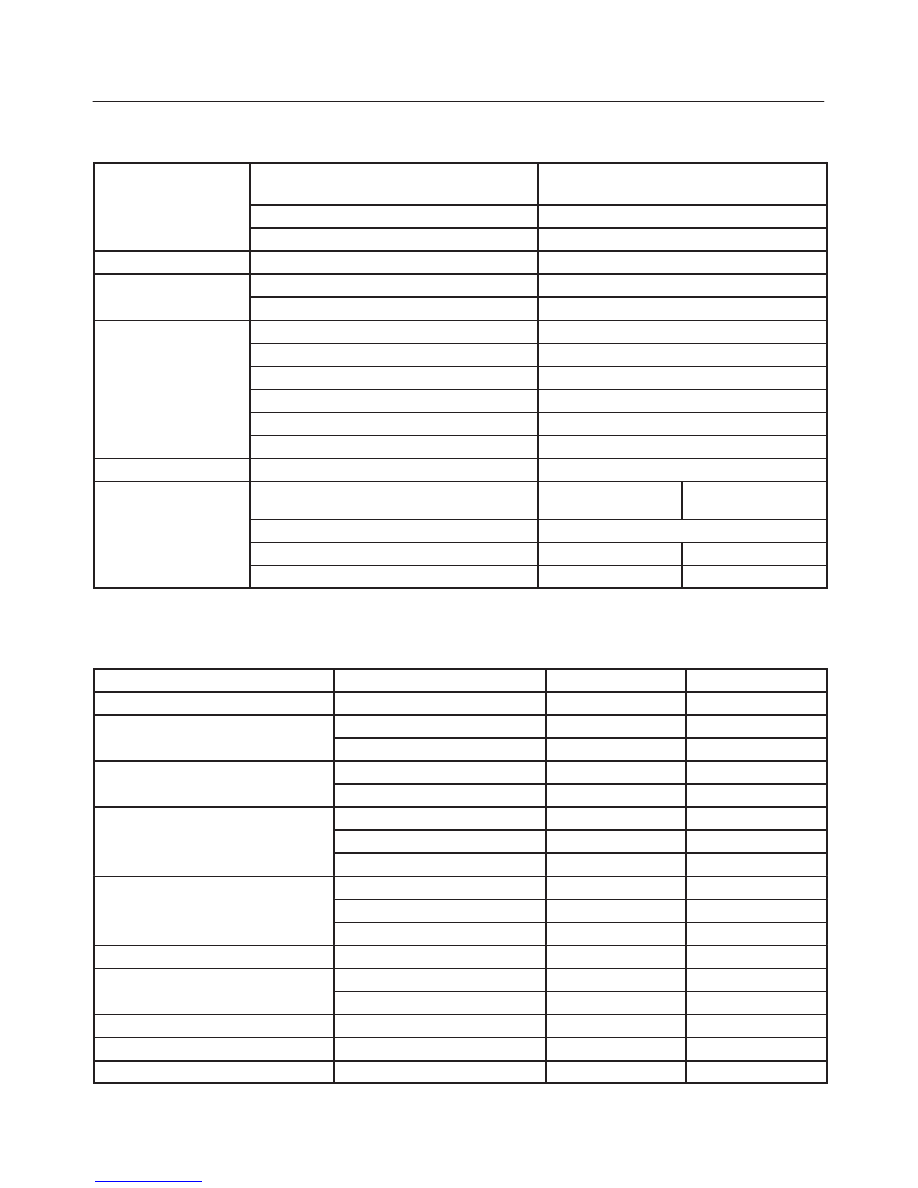
Maintenance Service Data
Service Data and Specifications
ENGINE
Valve clearance (cold): only V6–3.2L ENG
Intake 0.28
±
0.05 mm (0.011
±
0.002 in)
Exhaust 0.3
±
0.05 mm (0.012
±
0.002 in)
Spark plug type
K16PR-P11/PK16PR11/RC10PYP4
Spark plug gap
1.05 mm (0.04 in)
CLUTCH
Clutch pedal free play
5-15 mm (0.20-0.59 in)
BRAKE
Brake pedal free play
6-10 mm (0.24-0.39 in)
Parking brake travel
6-7 notches
WHEEL ALIGNMENT
Toe-in (Front)
0
±
2 mm (0
±
0.08 in)
Toe-in (Rear)
0
±
5 mm (0
±
0.2 in)
Camber (Front)
0
°
±
30’
Camber (Rear)
0
°
±
1
°
Caster (Front)
2
°
30’
±
45’
Toe–Axis (Rear)
±
1
°
PROPELLER SHAFT
Flange torque
63 N·m (46 lb ft)
WHEEL AND TIRES
Size
P215/75R15,
P235/75R15
P245/70R16
Wheel nut torque
118 N·m (87 lb ft)
Tire inflation pressure (Front)
200 kPa (29 psi)
180 kPa
* Tire inflation pressure (Rear)
200 kPa (29 psi)
180 kPa
* Unless otherwise specified on tire information label on the vehicle.
Approximate Capacities
Items
Metric Measure
U.S. Measure
Fuel tank
80 L
21.1 Gal.
* Crankcase (V6–3.2L ENGINE)
Oil Change with Filter
4.7 L
5.0 Qt
Oil Change without Filter
4.0 L
4.2 Qt
* Crankcase (L4–2.2L ENGINE)
Oil Change with Filter
4.5 L
4.8 Qt
Oil Change without Filter
4.2 L
4.4 Qt
Coolant
M/T (V6–3.2L ENG)
11.0 L
11.6 Qt
M/T (L4–2.2L ENG)
6.9 L
7.3 Qt
A/T
11.1 L
11.7 Qt
Transmission
Manual (V6–3.2L ENG)
2.95 L
3.1 Qt
Manual (L4–2.2L ENG)
2.13 L
2.25 Qt
Automatic
8.6 L
9.1 Qt
Transfer
1.45 L
1.5 Qt
Axle
Rear
1.77 L
1.87 Qt
Front
1.25 L
1.33 Qt
Shift on the fly system
0.12 L
0.13 Qt
Power steering
1.0 L
1.1 Qt
Air conditioning (R-134a)
0.6 L
1.32 Qt
*Crankcase capacities shown are approximate refill capacities. After refill, recheck oil level.
HEATING, VENTILATION AND AIR CONDITIONING (HVAC)
1A–1
RODEO
HEATING, VENTILATION AND AIR
CONDITIONING (HVAC)
HVAC SYSTEMS
CONTENTS
Service Precaution
1A–2
. . . . . . . . . . . . . . . . . . . . . .
Heating and Ventilation System
1A–2
. . . . . . . . . . .
General Description
1A–2
. . . . . . . . . . . . . . . . . . . .
Wiring Diagram
1A–6
. . . . . . . . . . . . . . . . . . . . . . .
Diagnosis
1A–7
. . . . . . . . . . . . . . . . . . . . . . . . . . . . .
Individual Inspection
1A–11
. . . . . . . . . . . . . . . . . . .
Heater Unit
1A–13
. . . . . . . . . . . . . . . . . . . . . . . . . . . . .
Heater Unit and Associated Parts
1A–13
. . . . . . . .
Removal
1A–13
. . . . . . . . . . . . . . . . . . . . . . . . . . . . .
Installation
1A–14
. . . . . . . . . . . . . . . . . . . . . . . . . . . .
Heater Core and / or Mode Door
1A–14
. . . . . . . . . .
Disassembled View
1A–14
. . . . . . . . . . . . . . . . . . . .
Removal
1A–14
. . . . . . . . . . . . . . . . . . . . . . . . . . . . .
Inspection
1A–15
. . . . . . . . . . . . . . . . . . . . . . . . . . . .
Installation
1A–15
. . . . . . . . . . . . . . . . . . . . . . . . . . . .
Heater Mode Control Link Unit
1A–16
. . . . . . . . . . . .
Disassembled View
1A–16
. . . . . . . . . . . . . . . . . . . .
Removal
1A–16
. . . . . . . . . . . . . . . . . . . . . . . . . . . . .
Installation
1A–17
. . . . . . . . . . . . . . . . . . . . . . . . . . . .
Heater Temperature Control Link Unit
1A–17
. . . . . .
Disassembled View
1A–17
. . . . . . . . . . . . . . . . . . . .
Removal
1A–17
. . . . . . . . . . . . . . . . . . . . . . . . . . . . .
Installation
1A–18
. . . . . . . . . . . . . . . . . . . . . . . . . . . .
Blower Assembly
1A–18
. . . . . . . . . . . . . . . . . . . . . . . .
Blower Assembly and Associated Parts
1A–18
. .
Removal
1A–18
. . . . . . . . . . . . . . . . . . . . . . . . . . . . .
Installation
1A–19
. . . . . . . . . . . . . . . . . . . . . . . . . . . .
Blower Link Unit and / or Mode door
1A–19
. . . . . . .
Disassembled View
1A–19
. . . . . . . . . . . . . . . . . . . .
Removal
1A–19
. . . . . . . . . . . . . . . . . . . . . . . . . . . . .
Installation
1A–20
. . . . . . . . . . . . . . . . . . . . . . . . . . . .
Blower Motor
1A–21
. . . . . . . . . . . . . . . . . . . . . . . . . . .
Blower Motor and Associated Parts
1A–21
. . . . . .
Removal
1A–21
. . . . . . . . . . . . . . . . . . . . . . . . . . . . .
Installation
1A–21
. . . . . . . . . . . . . . . . . . . . . . . . . . . .
Rear Heater Duct, Defroster Nozzle and
Ventilation Duct
1A–22
. . . . . . . . . . . . . . . . . . . . . . . . .
Rear Heater Duct, Defroster Nozzle,
Ventilation Duct and Associated Parts
1A–22
. . .
Removal
1A–22
. . . . . . . . . . . . . . . . . . . . . . . . . . . . .
Installation
1A–23
. . . . . . . . . . . . . . . . . . . . . . . . . . . .
Control Lever Assembly and / or Control
Cable
1A–23
. . . . . . . . . . . . . . . . . . . . . . . . . . . . . . . . .
Control Lever Assembly, Control Cable and
Associated Parts
1A–23
. . . . . . . . . . . . . . . . . . . . . .
Removal
1A–24
. . . . . . . . . . . . . . . . . . . . . . . . . . . . .
Installation
1A–25
. . . . . . . . . . . . . . . . . . . . . . . . . . . .
Control Panel Illumination Bulb
1A–26
. . . . . . . . . . . .
Control Panel Illumination Bulb and
Associated Parts
1A–26
. . . . . . . . . . . . . . . . . . . . . .
Removal
1A–26
. . . . . . . . . . . . . . . . . . . . . . . . . . . . .
Installation
1A–26
. . . . . . . . . . . . . . . . . . . . . . . . . . . .
Resistor
1A–26
. . . . . . . . . . . . . . . . . . . . . . . . . . . . . . . .
Resistor and Associated Parts
1A–26
. . . . . . . . . .
Removal
1A–26
. . . . . . . . . . . . . . . . . . . . . . . . . . . . .
Installation
1A–26
. . . . . . . . . . . . . . . . . . . . . . . . . . . .
Air Conditioning System
1A–27
. . . . . . . . . . . . . . . . . .
General Description
1A–27
. . . . . . . . . . . . . . . . . . . . .
Diagnosis
1A–35
. . . . . . . . . . . . . . . . . . . . . . . . . . . . . .
Individual Inspection
1A–44
. . . . . . . . . . . . . . . . . . . . .
General Repair Procedure
1A–45
. . . . . . . . . . . . . .
Leak Check
1A–47
. . . . . . . . . . . . . . . . . . . . . . . . . . .
Compressor Assembly
1A–52
. . . . . . . . . . . . . . . . . . .
Compressor Assembly and Associated
Parts
1A–52
. . . . . . . . . . . . . . . . . . . . . . . . . . . . . . . .
Removal
1A–52
. . . . . . . . . . . . . . . . . . . . . . . . . . . . .
Installation
1A–53
. . . . . . . . . . . . . . . . . . . . . . . . . . . .
New Compressor Installation
1A–53
. . . . . . . . . . . .
Condenser Assembly
1A–54
. . . . . . . . . . . . . . . . . . . .
Condenser Assembly and Associated
Parts
1A–54
. . . . . . . . . . . . . . . . . . . . . . . . . . . . . . . .
Removal
1A–54
. . . . . . . . . . . . . . . . . . . . . . . . . . . . .
Installation
1A–54
. . . . . . . . . . . . . . . . . . . . . . . . . . . .
Condenser Fan Motor
1A–55
. . . . . . . . . . . . . . . . . . . .
Condenser Fan Motor and Associated
Parts
1A–55
. . . . . . . . . . . . . . . . . . . . . . . . . . . . . . . .
Removal
1A–55
. . . . . . . . . . . . . . . . . . . . . . . . . . . . .
Installation
1A–55
. . . . . . . . . . . . . . . . . . . . . . . . . . . .
Receiver / Drier
1A–56
. . . . . . . . . . . . . . . . . . . . . . . . .
Receiver / Drier and Associated Parts
1A–56
. . . .
Removal
1A–56
. . . . . . . . . . . . . . . . . . . . . . . . . . . . .
Installation
1A–56
. . . . . . . . . . . . . . . . . . . . . . . . . . . .
Pressure Switch
1A–57
. . . . . . . . . . . . . . . . . . . . . . . . .
Pressure Switch and Associated Parts
1A–57
. . .
Нет комментариевНе стесняйтесь поделиться с нами вашим ценным мнением.
Текст