Isuzu Rodeo UE. Manual — part 8
1A–2
HEATING, VENTILATION AND AIR CONDITIONING (HVAC)
Removal
1A–57
. . . . . . . . . . . . . . . . . . . . . . . . . . . . .
Installation
1A–57
. . . . . . . . . . . . . . . . . . . . . . . . . . . .
Evaporator Assembly
1A–58
. . . . . . . . . . . . . . . . . . . .
Evaporator Assembly and Associated
Parts
1A–58
. . . . . . . . . . . . . . . . . . . . . . . . . . . . . . . .
Removal
1A–58
. . . . . . . . . . . . . . . . . . . . . . . . . . . . .
Installation
1A–59
. . . . . . . . . . . . . . . . . . . . . . . . . . . .
Electronic Thermostat, Evaporator Core
and/or Expansion Valve
1A–59
. . . . . . . . . . . . . . . . .
Disassembled View
1A–59
. . . . . . . . . . . . . . . . . . . .
Removal
1A–60
. . . . . . . . . . . . . . . . . . . . . . . . . . . . .
Installation
1A–60
. . . . . . . . . . . . . . . . . . . . . . . . . . . .
Refrigerant Line
1A–61
. . . . . . . . . . . . . . . . . . . . . . . . .
Refrigerant Line and Associated Parts
1A–61
. . . .
Removal
1A–62
. . . . . . . . . . . . . . . . . . . . . . . . . . . . .
Installation
1A–62
. . . . . . . . . . . . . . . . . . . . . . . . . . . .
Main Data And Specifications
1A–62
. . . . . . . . . . . . .
Compressor
1A–65
. . . . . . . . . . . . . . . . . . . . . . . . . . . .
Service Precaution
1A–65
. . . . . . . . . . . . . . . . . . . .
General Description
1A–65
. . . . . . . . . . . . . . . . . . . . .
Diagnosis
1A–66
. . . . . . . . . . . . . . . . . . . . . . . . . . . . . .
Magnetic Clutch Assembly (DKV-14D Type)
1A–67
Parts Location View
1A–67
. . . . . . . . . . . . . . . . . . . .
Removal
1A–67
. . . . . . . . . . . . . . . . . . . . . . . . . . . . .
Inspection and Repair
1A–68
. . . . . . . . . . . . . . . . . .
Installation
1A–69
. . . . . . . . . . . . . . . . . . . . . . . . . . . .
Compressor Oil
1A–70
. . . . . . . . . . . . . . . . . . . . . . . . .
Oil Specification
1A–70
. . . . . . . . . . . . . . . . . . . . . . .
Handling of Oil
1A–70
. . . . . . . . . . . . . . . . . . . . . . . .
Compressor Oil Check
1A–70
. . . . . . . . . . . . . . . . .
Checking and Adjusting Oil Quantity
for Used Compressor
1A–70
. . . . . . . . . . . . . . . . . .
Checking and Adjusting for Compressor
Replacement
1A–71
. . . . . . . . . . . . . . . . . . . . . . . . .
Contamination of Compressor Oil
1A–71
. . . . . . . .
Oil Return Operation
1A–71
. . . . . . . . . . . . . . . . . . .
Replacement of Component Parts
1A–71
. . . . . . .
Main Data and Specifications
1A–72
. . . . . . . . . . . . .
Special Tools
1A–74
. . . . . . . . . . . . . . . . . . . . . . . . . . .
Service Precaution
WARNING: THIS VEHICLE HAS A SUPPLEMENTAL
RESTRAINT SYSTEM (SRS). REFER TO THE SRS
COMPONENT AND WIRING LOCATION VIEW IN
ORDER TO DETERMINE WHETHER YOU ARE
PERFORMING SERVICE ON OR NEAR THE SRS
COMPONENTS OR THE SRS WIRING. WHEN YOU
ARE PERFORMING SERVICE ON OR NEAR THE SRS
COMPONENTS OR THE SRS WIRING, REFER TO
THE SRS SERVICE INFORMATION. FAILURE TO
FOLLOW WARNINGS COULD RESULT IN POSSIBLE
AIR BAG DEPLOYMENT, PERSONAL INJURY, OR
OTHERWISE UNNEEDED SRS SYSTEM REPAIRS.
CAUTION: Always use the correct fastener in the
proper location. When you replace a fastener, use
ONLY the exact part number for that application.
ISUZU will call out those fasteners that require a
replacement after removal. ISUZU will also call out
the fasteners that require thread lockers or thread
sealant. UNLESS OTHERWISE SPECIFIED, do not
use supplemental coatings (Paints, greases, or other
corrosion inhibitors) on threaded fasteners or
fastener joint interfaces. Generally, such coatings
adversely affect the fastener torque and the joint
clamping force, and may damage the fastener. When
you install fasteners, use the correct tightening
sequence and specifications. Following these
instructions can help you avoid damage to parts and
systems.
Heating and Ventilation System
General Description
Heater
When the engine is warming up, the warmed engine
coolant is sent out into the heater core. The heater system
supplies warm air into the passenger compartment to
warm it up.
Outside air is circulated through the heater core of the
heater unit and then back into the passenger
compartment. By controlling the mixture of outside air and
heater core air, the most comfortable passenger
compartment temperature can be selected and
maintained.
The temperature of warm air sent to the passenger
compartment is controlled by the temperature control
knob. This knob acts to open and close the air mix door,
thus controlling the amount of air passed through the
heater core.
The air selector knob, with its different modes, also allows
you to select and maintain the most comfortable
passenger compartment temperature.
The air source select lever is used to select either
“FRESH” for the introduction of the outside air, or “CIRC”
for the circulation of the inside air. When the lever is set to
“FRESH”, the outside air is always taken into the
passenger compartment. When setting the lever to
“CIRC” position, the circulation of air is restricted only to
the inside air with no introduction of the outside air and the
air in the passenger compartment gets warm quickly.
However, the lever is normally set to “FRESH” to prevent
the windshield from clouding.

HEATING, VENTILATION AND AIR CONDITIONING (HVAC)
1A–3
840RW002
Legend
(1) Defroster Nozzle
(2) Ventilation Duct
(3) Blower Assembly
(4) Evaporator Assembly (With A/C)
(5) Duct (W/O A/C)
(6) Heater Unit
(7) Ventilation Lower Duct
(8) Lap Vent Duct
(9) Rear Heater Duct
1A–4
HEATING, VENTILATION AND AIR CONDITIONING (HVAC)
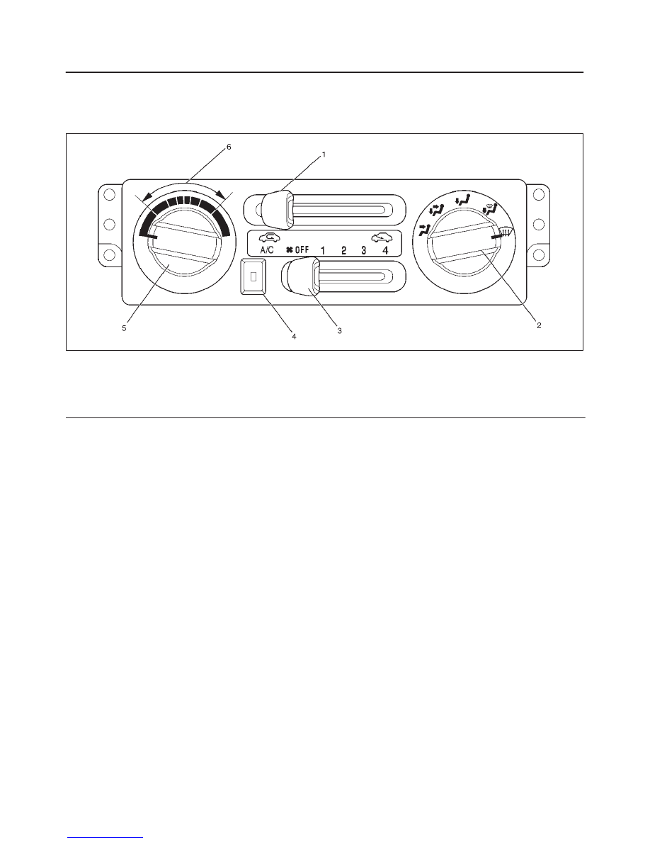
Control Lever Assembly
The control lever assembly has some cables to control
the mode and temperature of the heater unit and the
mode door for the air source of the blower assembly.
The fan control is used to control the amount of air sent
out by the resistor at four levels from “LOW” to “HIGH”.
865RW006
Legend
(1) Air Source Select Lever
(2) Air Select Knob
(3) Fan Control Lever (Fan Switch)
(4) Air Conditioning (A/C) Switch (W/ A/C)
(5) Temperature Control Knob
(6) Middle Position
Ventilation
Setting the air source select lever to “FRESH” position
allows the heating system to work with sending the fresh
air from outside.
The blower fan also serves to deliver fresh outside air to
the passenger compartment to assure adequate
ventilation.
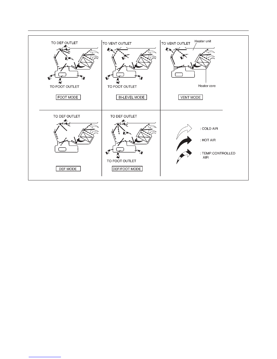
Air Select Knob
The air select knob allows you to direct heated air into the
passenger compartment through different outlets.
1. Vent – In this position, air is discharged from the
upper air outlet. Air quantity is controlled by the fan
control lever.
2. Bi-Level – In this position, air flow is divided between
the upper air outlets and the floor air outlets, with
warmer air delivered to the floor outlets than the air
delivered to the upper air outlets when the temp lever
is in middle position.
3. Foot – In this position, air flow is delivered to the foot,
while sending a small amount of air to the windshield.
4. Def/Foot – In this position, air flow is delivered to the
foot, while sending approx. 40% of total amount of air
to the windshield.
Selecting this mode allows air conditioning system to
work while the fan switch is turned to on position, even
if the A/C switch is off.
5. Defrost – In this position, most of the air is delivered
to the windshield and a small amount is delivered to
the side windows.
Selecting this mode allows air conditioning system to
work while the fan switch is turned to on position, even
if the A/C switch is off.
Moving the air source select lever to the “CIRC” position
provides quickest heat delivery by closing the blower
assembly mode door. In this position, outside air is not
delivered to the passenger compartment.
HEATING, VENTILATION AND AIR CONDITIONING (HVAC)
1A–5
C01RW001
Air Source Select Lever
The intake of outside air and the circulation of inside air
are controlled by sliding this lever left or right.
Fan Control Lever
This lever controls the blower motor speed to regulate the
amount of air delivered to the defrost, foot, and ventilation
ducts:
1. Low
2. Medium Low
3. Medium High
4. High
Temperature Control Knob
When the temperature control knob is in the “COLD”
position, the air mix door closes to block the flow air to the
heater core.
When the temperature control knob is in the “HOT”
position, the air mix door opens to allow air to pass
through the heater core and heat the passenger
compartment.
Placing the knob in a intermediate position will cause a
lesser or greater amount air to reach the heater core. In
this mode the passenger compartment temperature can
be regulated.
Нет комментариевНе стесняйтесь поделиться с нами вашим ценным мнением.
Текст