Isuzu Rodeo UE. Manual — part 624
SECURITY AND LOCKS
8H–7
Removal
1. Disconnect the battery ground cable.
2. Remove rear corner garnish.
3. Remove courtesy light lens.
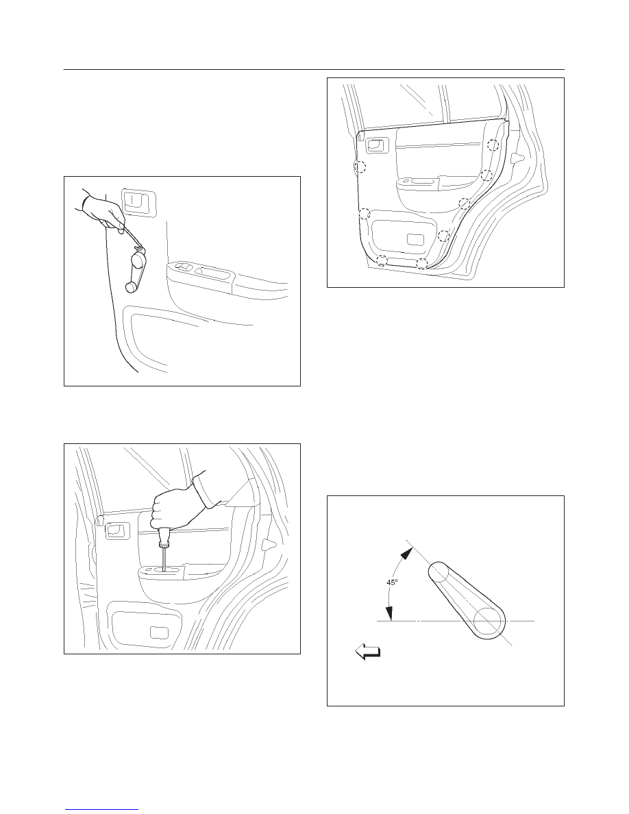
4. Remove window regulator handle.
f
Remove the clip on the rear side of the regulator
handle using a wire.
651RW003
5. Remove the screw while pulling the inside lever
toward you and then remove the inside handle.
6. Remove the 2 screws at the pull case and courtesy
light.
655RW003
7. Pull out the trim panel at the 8 clip positions.
f
Disconnect the power window switch connector
and courtesy light connector.
655RW002
8. Remove power window switch, if equipped.
9. Remove bracket.
10. Remove waterproof sheet.
f
Taking notice of the door harness, peel the
waterproof sheet off the door panel carefully.
11. Disconnect the locking links and remove the door lock
assembly fixing screws to remove the door lock
assembly.
Installation
To install, follow the removal steps in the reverse order,
noting the following points.
1. Apply chassis grease to the lock assembly and striker
moving surface.
2. Install the regulator handle as shown in the
illustration, if equipped without power windows.
631RW005
3. Check that the door lock operates smoothly.
8H–8
SECURITY AND LOCKS
Rear Outside Handle
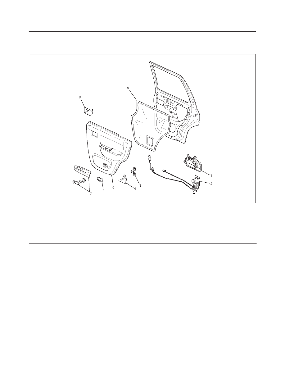
Rear Outside Handle and Associated Parts
655RW005
Legend
(1) Outside Handle
(2) Door Lock Assembly
(3) Bracket
(4) Rear Corner Garnish
(5) Door Trim Panel
(6) Courtesy Light Lens
(7) Power Window Switch/Window Regulator
Handle
(8) Inside Handle
(9) Waterproof Sheet
Removal
1. Disconnect the battery ground cable.
2. Remove the door trim panel.
f
Refer to Rear Door Lock Assembly in this section.
3. Remove the waterproof sheet.
f
Taking notice of the door harness, peel the
waterproof sheet off the door panel carefully.
4. Disconnect the locking link and remove fixing bolts to
remove the outside handle.
Installation
To install, follow the removal steps in the reverse order,
noting the following point:
1. Check that the outside handle operates smoothly.
SECURITY AND LOCKS
8H–9
Tailgate Lock and Hatchgate Lock
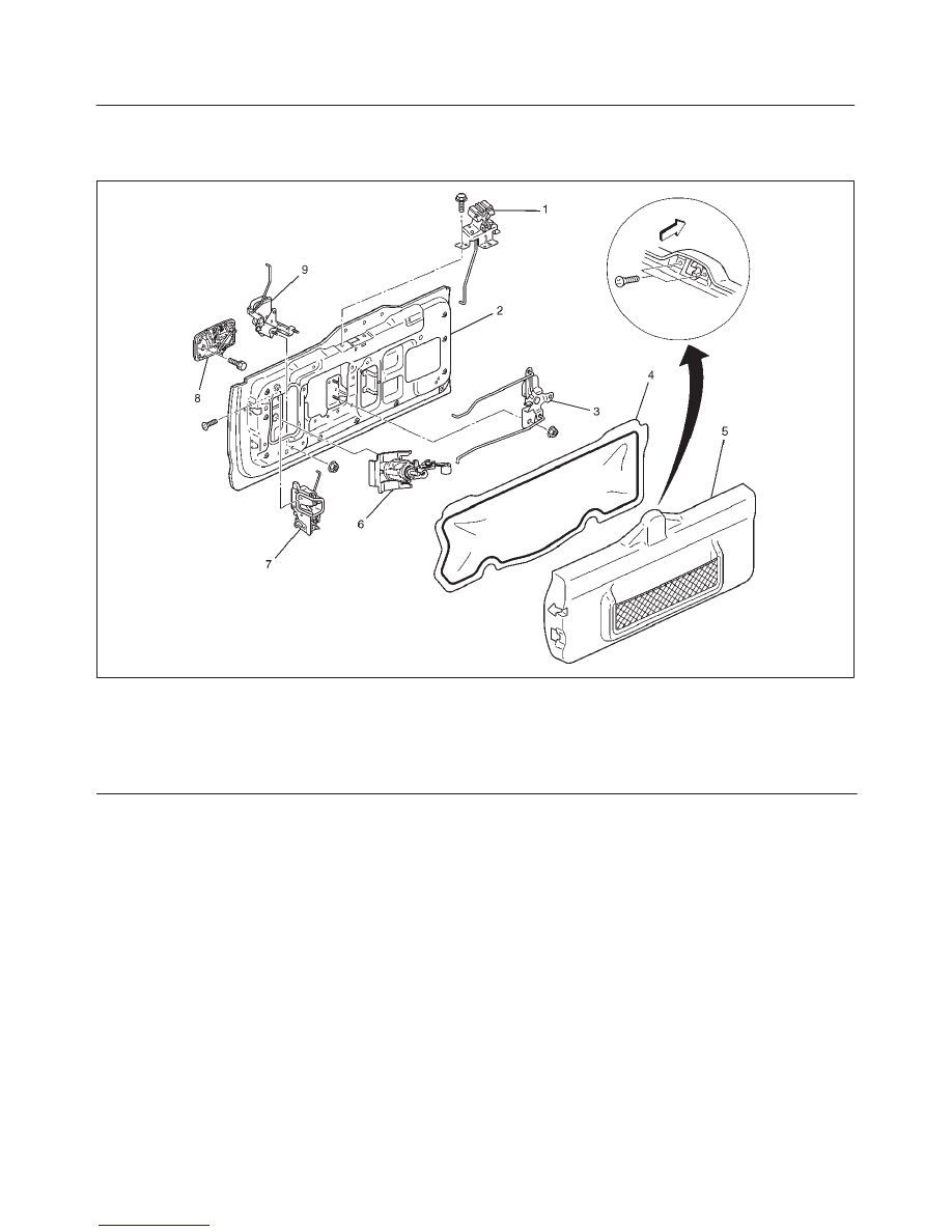
Tailgate Lock, Hatchgate Lock and Associated Parts
681RW005
Legend
(1) Hatchgate Lock Assembly
(2) Tailgate Assembly
(3) Tailgate Lock Relay Lever
(4) Waterproof sheet
(5) Trim Cover Assembly
(6) Key Cylinder
(7) Tailgate Lock Assembly
(8) Ouside Handle
(9) Hatchgate Lock Actuator Assembly
8H–10 SECURITY AND LOCKS
Removal
1. Disconnect the battery ground cable.
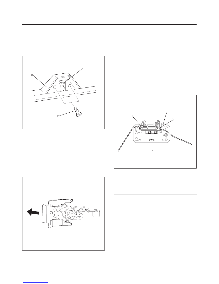
2. Remove tailgate trim cover assembly (3).
f
Remove the 2 screws (2) holding the hatchgate lock
assembly (1) first, and pull up the trim cover while
detaching the clips from tailgate panel.
683RW001
3. Remove waterproof sheet.
f
Remove waterproof sheet, exercising special care
so as not to break it them.
4. Remove hatchgate lock.
f
Disconnect the lock link and connector and remove
the 3 fixing bolts.
5. Remove key cylinder.
f
Disconnect the lock links.
f
Remove the key cylinder retaining clip with screw
driver to remove the key cylinder.
683RW002
6. Remove hatchgate lock actuator assembly.
f
Disconnect the actuator harness connector.
f
Remove 2 bolts holding hatchgate lock actuator
assembly from inside.
7. Remove outside handle.
f
Remove the 2 bolts holding the outside handle from
inside.
8. Remove tailgate lock assembly.
f
Remove 3 screws holding the lock assembly.
Installation
To install, follow the removal steps in the reverse order,
noting the following points:
1. When setting up links, pay attention to the position
and direction of the links.
683RW003
Legend
(1) Tailgate Lock Link
(2) Outside Handle
(3) Key Cylinder Link
(4) Cancel Mechanism
2. Apply chassis grease to the lock assembly and striker
moving surface.
3. Check that the tailgate lock operates correctly after
installing it.
Нет комментариевНе стесняйтесь поделиться с нами вашим ценным мнением.
Текст