Isuzu Rodeo UE. Manual — part 623
SECURITY AND LOCKS
8H–3
Removal
1. Disconnect the battery ground cable.
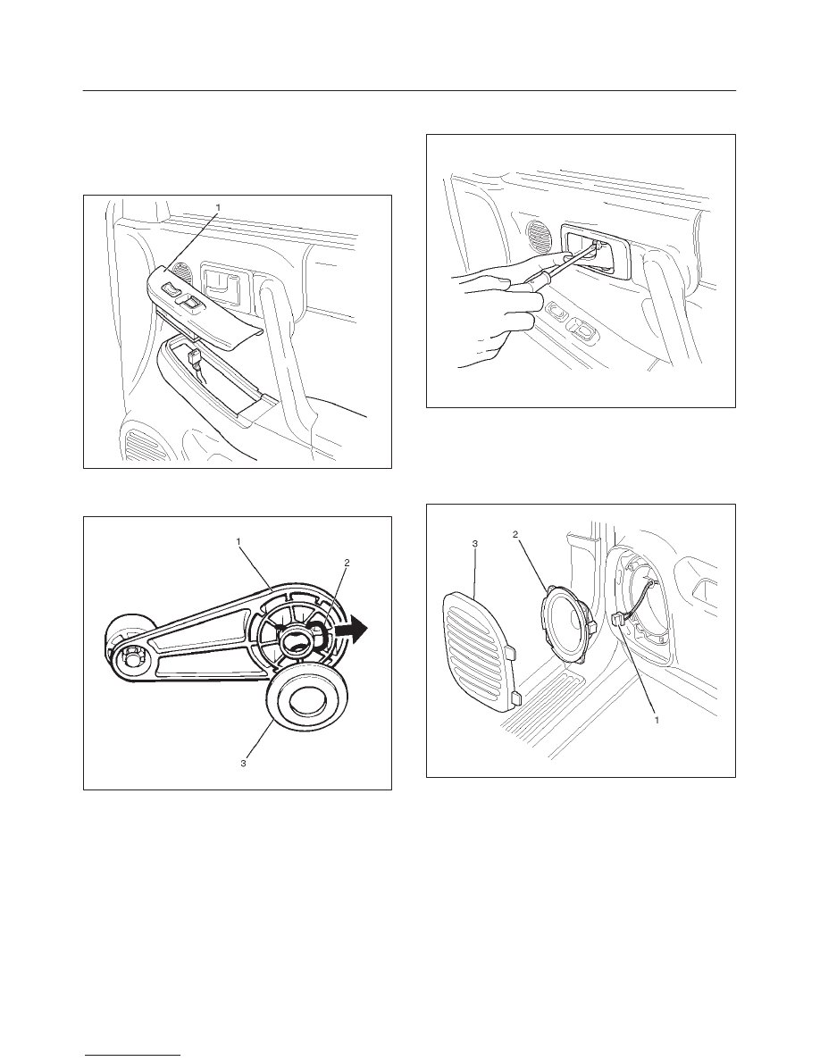
2. Remove power window switch (1)/regulator handle.
f
Pry out the power window switch and remove the
connectors.
635RW004
f
To remove the regulator handle (1), remove the clip
(2), at the root of the handle by using wire with hook.
631RW004
3. Remove the screw while pulling the inside lever
toward you and then remove the inside handle.
632RW003
4. Remove speaker grille (3).
f
Pull out the front side of the grille.
5. Remove speaker assembly (2).
f
Remove 4 screws and disconnect the speaker
harness connector (1).
635RW002
8H–4
SECURITY AND LOCKS
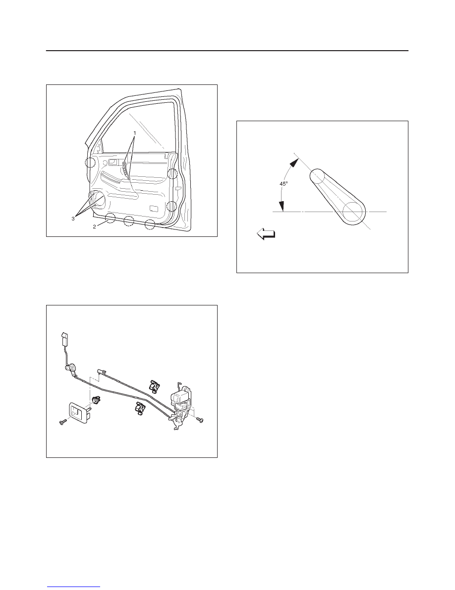
6. Remove courtesy light lens.
7. Remove 5 screws (1), (3) and pull out the door trim
panel at the 6 clip (2) positions.
635RW007
8. Remove the waterproof sheet.
f
Taking notice of the door harness, peel the
waterproof sheet off the door panel carefully.
9. Raise the glass up to the uppermost position, and
then remove the rear guide rail.
10. Disconnect the locking links then remove the door
lock assembly fixing screws and door lock assembly.
652RW002
Installation
To install, follow the removal steps in the reverse order,
noting the following points:
1. Apply chassis grease to the lock assembly and striker
moving surface.
2. Install the regulator handle as shown in the
illustration, if equipped without power windows.
631RW005
3. Check that the door lock operates smoothly.
SECURITY AND LOCKS
8H–5
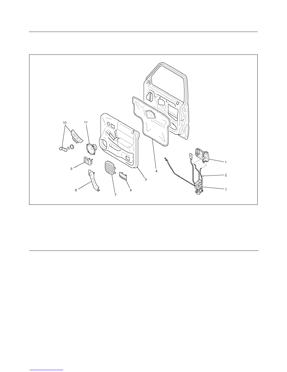
Front Outside Handle
Front Outside Handle and Associated Parts
635RW008
Legend
(1) Outside Handle
(2) Door Locking Link
(3) Door Lock Assembly
(4) Waterproof Sheet
(5) Door Trim Panel
(6) Courtesy Light Lens
(7) Speaker Grille
(8) Grip Cover
(9) Inside Handle
(10) Power Window Switch/Window Regulator
Handle
(11) Speaker Assembly
Removal
1. Disconnect the battery ground cable.
2. Remove the door trim panel.
f
Refer to Front Door Lock Assembly in this section.
3. Remove the waterproof sheet.
f
Taking notice of the door harness, peel the
waterproof sheet off the door panel carefully.
4. Disconnect the locking links and remove the outside
handle.
5. Remove the fixing clip to remove the door lock
cylinder.
Installation
To install, follow the removal steps in the reverse order,
noting the following points:
1. Be sure to install the door lock cylinder at a right angle
to the outside handle.
2. Check for smooth outside handle and lock cylinder
operation.
8H–6
SECURITY AND LOCKS
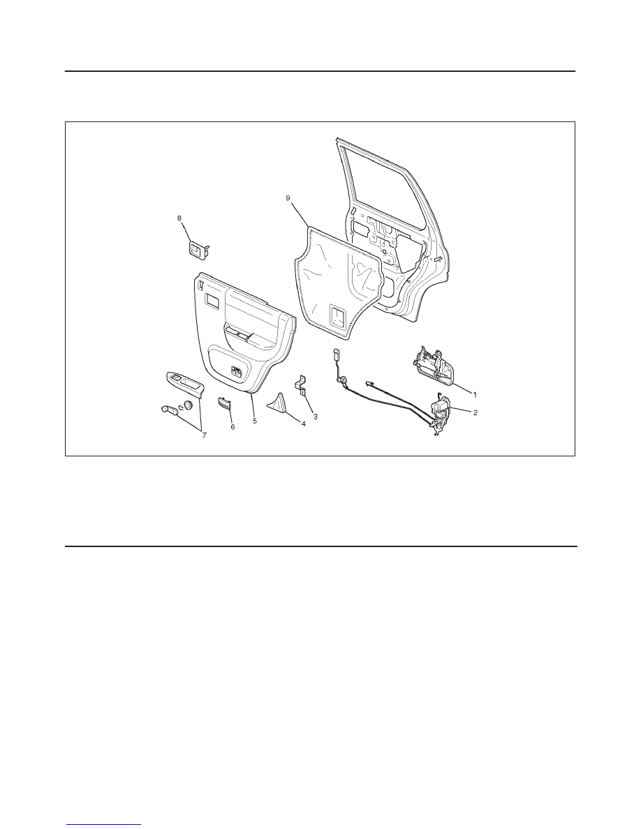
Rear Door Lock Assembly
Rear Door Lock Assembly and Associated Parts
655RW005
Legend
(1) Outside Handle
(2) Door Lock Assembly
(3) Bracket
(4) Rear Corner Garnish
(5) Door Trim Panel
(6) Courtesy Light Lens
(7) Power Window Switch/Window Regulator
Handle
(8) Inside Handle
(9) Waterproof Sheet
Нет комментариевНе стесняйтесь поделиться с нами вашим ценным мнением.
Текст