Isuzu Rodeo UE. Manual — part 60
DIFFERENTIAL (REAR)
4A2–5
Axle Housing
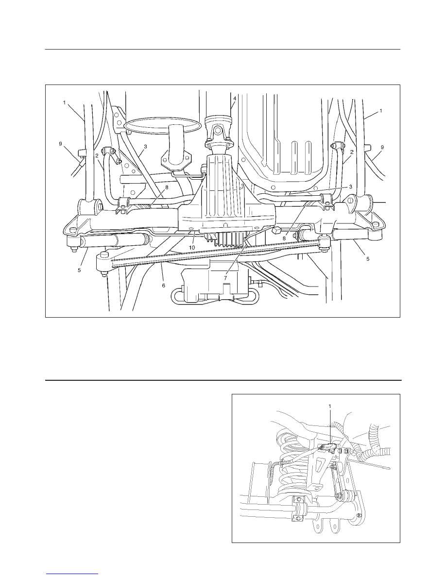
Axle Housing and Associated Parts
420RW030
Legend
(1) Lower Link
(2) Stabilizer
(3) Upper Link
(4) Rear Propeller shaft
(5) Shock Absorber
(6) Lateral Rod
(7) Brake Hose
(8) Coil Spring
(9) Parking Cable
(10) Axle Assembly
Removal
1. Raise the vehicle and support it with suitable safety
stands.
The hoist must remain under the rear axle housing.
2. Take out brake fluid. Refer to Hydraulic Brakes in
Brake section.
3. Remove rear wheels and tires. Refer to Wheel
Replacement in Suspension section.
4. Remove propeller shaft. Refer to Rear Propeller
Shaft in this section.
5. Drain the rear axle oil into a proper container.
6. Remove parking brake cable, release the connection
between the cable fixing clip equalizer. Refer to
Parking Brakes in Brake section.
7. Move the clip aside and pull out the breather hose.
8. Disconnect the ABS connectors (1) and remove the
brackets attached to the frame and center link.
350RW023
4A2–6
DIFFERNTIAL (REAR)
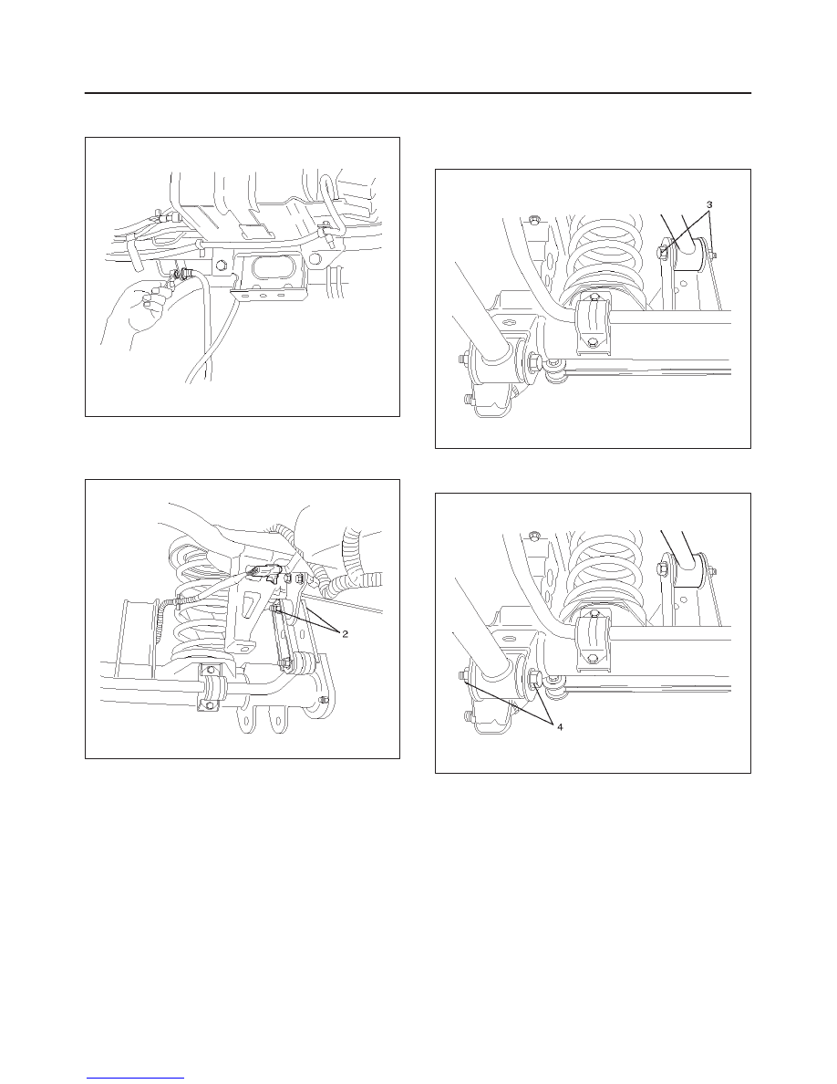
9. Loosen the brake tube flare nut, remove the clip and
take out the brake tube.
350RW020
10. Remove the shock absorber.
11. Remove the stabilizer linkage mounting bolts and
nuts (2) from the frame side.
350RW024
12. Remove the lateral rod fixing bolt and nut from the
frame.
13. Remove the upper link mounting bolt and nut (3) from
the axle housing.
460RW015
14. Remove the lower link fixing bolt and nut (4) from the
axle housing.
460RW016
15. Jack down and remove the coil spring and insulator.
16. Axle housing assembly can be separated from the
vehicle on completion of steps 1 – 15.
17. Remove the brake caliper fixing bolt, loosen the flare
nut, release the clip and take out the brake caliper
together with the flexible hose.
18. Remove brake disc.
19. Remove antilock brake system speed sensor fixing
bolt and the clip and bracket on the axle housing.
20. Remove the brake pipe clip and fixing bolt on the axle
housing and take out the brake pipe.
DIFFERENTIAL (REAR)
4A2–7
Installation
1. Install brake pipe.
2. Connect Antilock brake system (ABS) speed sensor
and harness, refer to 4–Wheel Anti–Lock Brake
System (ABS) in Brake section.
3. Install brake disc.
4. Install brake caliper. Refer to Disk Brakes in Brake
section.
5. Install axle housing assembly.
6. Install coil spring and insulator.
7. Install the lower link fixing bolt and nut to the axle
housing. For the procedures in items 7–11, refer to
Suspension section.
8. Install the upper link bolt and nut to the axle housing.
9. Install the lateral rod fixing nut and bolt to the frame
side.
10. Install the stabilizer linkage mounting nut and bolt to
the frame side.
11. Install the shock absorber.
12. Install brake tube flare nut, Refer to Disk Brakes in
Brake section.
13. Install ABS connector and bracket.
14. Connect breather hose.
15. Install parking brake cable, Refer to Parking Brakes in
Brake section.
16. Bleed brakes. Refer to Hydraulic Brakes in Brake
section.
Axle Shaft, Oil Seal and Bearing
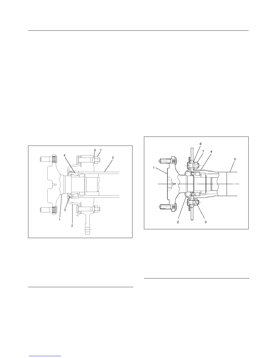
Axle Shaft and Associated Parts
Disc Brake Model
420RW008
Legend
(1) Axle Shaft
(2) Backing Plate
(3) Oil Seal
(4) Bearing
(5) Axle Housing
(6) Lock Washer
(7) Nut
Drum Brake Model
420RX001
Legend
(1) Axle Shaft
(2) Backing Plate
(3) Oil Seal
(4) Bearing
(5) Axle Housing
(6) Lock Washer
(7) Nut
4A2–8
DIFFERNTIAL (REAR)
Removal
1. Raise the vehicle.
2. Remove rear wheels and brake calipers or drums.
Do not let calipers hang from the vehicle by the brake
line or hose. Wire them to frame of vehicle to prevent
damage.
3. Remove four nuts and lockwashers.
4. Remove shaft assembly from the axle housing.
5. Remove snap ring and bearing cup.
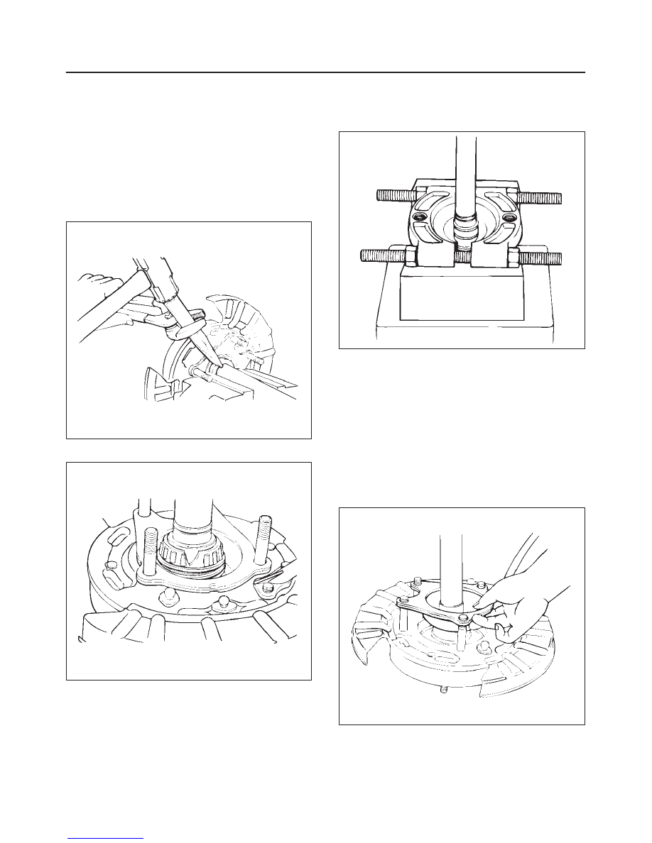
6. Break retainer ring with hammer and chisel.
420RS026
7. Break bearing cage with hammer and chisel.
420RS027
8. Remove oil seal, retainer, and emergency brake
assembly.
9. Remove inner race from shaft with OTC–1126
bearing splitter and press.
420RS028
Inspection
f
Shaft for spalling or grooves from seal wear.
f
Retainer – bent or damaged.
f
Replace items if required.
Installation
1. Emergency brake assembly.
2. Install retainer.
Note direction – do not install backwards.
420RS029
Нет комментариевНе стесняйтесь поделиться с нами вашим ценным мнением.
Текст