Isuzu Rodeo UE. Manual — part 363

6E2–207
RODEO 6VD1 3.2L ENGINE DRIVEABILITY AND EMISSIONS
DTC P0157 – HO2S Circuit Low Voltage Bank 2 Sensor 2
(Cont'd)
Step
No
Yes
Value(s)
Action
6
1. Ignition “OFF.”
2. Leave the PCM and HO2S 2 disconnected.
3. Check for continuity between the high and low
signal circuits.
Was there continuity between the high and low circuits?
—
Go to
Step 7
Go to
Step 8
7
Repair the short between the high and low circuits.
Is the action complete?
—
Verify repair
—
8
1. Ignition “OFF.”
2. Reconnect the PCM, leave HO2S 2 disconnected.
3. Ignition “ON.”
Does the Tech 2 indicate Bank 2 HO2S 2 voltage near
the specified value?
425-475 mV
Refer to
Diagnostic
Aids
Go to
Step 9
9
Replace the PCM.
IMPORTANT: The replacement PCM must be
programmed. Refer to
On-Vehicle Service in
Powertrain Control Module and Sensors for
procedures.
And also refer to latest service bulletin.
Check to see if the Latest software is released or not.
And then Down Load the LATEST PROGRAMMED
SOFTWARE to the replacement PCM.
Is the action complete?
—
Verify repair
—
6E2–208
RODEO 6VD1 3.2L ENGINE DRIVEABILITY AND EMISSIONS
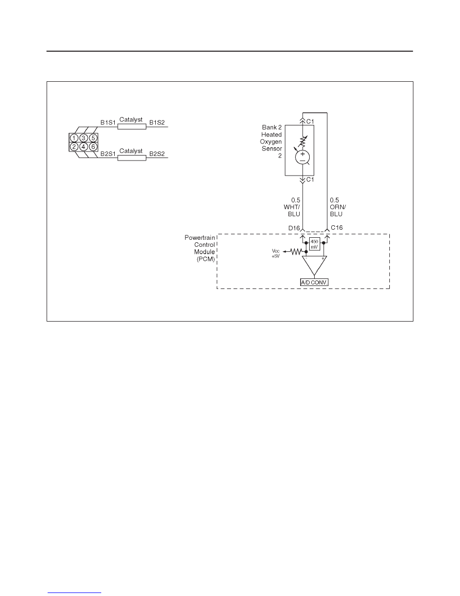
Diagnostic Trouble Code (DTC) P0158 HO2S Circuit High Voltage Bank 2
Sensor 2
D06RW065
Circuit Description
To control emissions of hydrocarbons (HC), carbon
monoxide (CO), and oxides of nitrogen (NOx), a
three-way catalytic converter is used. The catalyst within
the converter promotes a chemical reaction which
oxidizes the HC and CO present in the exhaust gas,
converting them into harmless water vapor and carbon
dioxide. The catalyst also reduces NOx, converting it to
nitrogen. The powertrain control module (PCM) has the
ability to monitor this process using the Bank 2 HO2S 1
and the Bank 2 HO2S 2 heated oxygen sensors. The
Bank 2 HO2S 1 sensor produces an output signal which
indicates the amount of oxygen present in the exhaust
gas entering the three-way catalytic converter. The Bank
2 HO2S 2 sensor produces an output signal which
indicates the oxygen storage capacity of the catalyst; this
in turn indicates the catalyst’s ability to convert exhaust
gases efficiently. If the catalyst is operating efficiently, the
Bank 2 HO2S 1 signal will be far more active than that
produced by the Bank 2 HO2S 2 sensor. If the Bank 2
HO2S 2 signal voltage remains excessively high for an
extended period of time, DTC P0158 will be set.
Conditions for Setting the DTC
f
No related DTCs.
f
Engine is operating in “closed loop.”
f
“Closed loop” commanded air/fuel ratio is between
14.5 and 14.8.
f
Engine coolant temperature is above 60
°
C (140
°
F).
f
Throttle angle is between 3% and 19%.
f
Bank 2 HO2S 2 signal voltage remains above 952 mV
during normal “closed loop” operation for a total of 106
seconds over a 125-second period.
OR
f
Bank 2 HO2S 2 signal voltage remains above 500 mV
during deceleration fuel cutoff mode operation for up to
3 seconds.
Action Taken When the DTC Sets
f
The PCM will illuminate the malfunction indicator lamp
(MIL) the first time the fault is detected.
f
The PCM will store conditions which were present
when the DTC was set as Freeze Frame and in the
Failure Records data.
Conditions for Clearing the MIL/DTC
f
The PCM will turn the MIL “OFF” on the third
consecutive trip cycle during which the diagnostic has
been run and the fault condition is no longer present.
f
A history DTC P0158 will clear after 40 consecutive
warm-up cycles have occurred without a fault.
f
DTC P0158 can be cleared by using the Tech 2 “Clear
Info” function or by disconnecting the PCM battery
feed.

6E2–209
RODEO 6VD1 3.2L ENGINE DRIVEABILITY AND EMISSIONS
Diagnostic Aids
Check for the following conditions:
f
Fuel pressure – An excessively rich fuel mixture can
cause a DTC P0158 to be set. Refer to
Fuel System
Diagnosis.
f
Rich injector(s) – Perform “Injector Balance Test.”
f
Leaking injector – Refer to
Fuel System Diagnosis.
f
Evaporative emissions (EVAP) canister purge – Check
for fuel saturation. If full of fuel, check canister control
and hoses. Refer to
Evaporative Emission (EVAP)
Control System.
f
MAF sensor –The system can go rich if the MAF
sensor signal indicates an engine airflow
measurement that is not correct. Disconnect the MAF
sensor to see if a rich condition is corrected. If so,
replace the MAF sensor.
f
Check for a leaking fuel pressure regulator diaphragm
by checking the vacuum line to the regulator for the
presence of fuel. There should be no fuel in the
vacuum line.
f
TP sensor – An intermittent TP sensor output will
cause the system to go rich, due to a false indication
of the engine accelerating.
f
Shorted Heated Oxygen Sensor (HO2S) – If the HO2S
is internally shorted, the HO2S voltage displayed on
the Tech 2 will be over 1 volt. Try disconnecting the
affected HO2S with the key “ON,” engine “OFF.” If the
displayed HO2S voltage changes from over 1000 mV
to around 450 mV, replace the HO2S. Silicon
contamination of the HO2S can also cause a high
HO2S voltage to be indicated. This condition is
indicated by a powdery white deposit on the portion of
the HO2S exposed to the exhaust stream. If
contamination is noticed, replace the affected HO2S.
f
Open HO2S signal or low circuit, or faulty HO2S – A
poor connection or open in the HO2S signal or low
circuit can cause the DTC to set during deceleration
fuel cutoff mode operation. An HO2S which is faulty
and does not allow full voltage swing between the rich
and lean thresholds can also cause this condition.
Operate the vehicle while monitoring the HO2S voltage
with a Tech 2. If the HO2S voltage is limited within a
range between 300 mV to 600 mV, check the HO2S
signal and low circuit wiring and associated terminal
connections. If the wiring and connections are OK,
replace the HO2S.
f
If none of above conditions are present, replace the
affected HO2S.
Test Description
Number(s) below refer to the step number(s) on the
Diagnostic Chart.
3. DTC P0158 being set during deceleration fuel cutoff
mode operation may indicate a condition described
in the “Diagnostic Aids” above. If the DTC P0158
test passes while the Failure Records conditions are
being duplicated, an intermittent condition is
indicated.
Reviewing the Failure Records vehicle mileage since the
diagnostic test last failed may help determine how often
the condition that caused the DTC to be set occurs. This
may assist in diagnosing the condition.
DTC P0158 – HO2S Circuit High Voltage Bank 2 Sensor 2
Step
Action
Value(s)
Yes
No
1
Was the “On-Board Diagnostic (OBD) System Check”
performed?
—
Go to
Step 2
Go to
OBD
System
Check
2
1. Install the Tech 2.
2. Run the engine at operating temperature.
3. Operate the vehicle within parameters specified
under “Conditions for Setting the DTC” criteria
included in Diagnostic Support.
4. Using a Tech 2, monitor Bank 2 HO2S 2 voltage.
Does the Bank 2 HO2S 2 voltage remain above the
specified value?
952 mV (500
mV in
deceleration
fuel cut-out
mode)
Go to
Step 4
Go to
Step 3
3
1. Ignition “ON.”
2. Review and record Tech 2 Failure Records data.
3. Operate the vehicle within Failure Records
conditions as noted.
4. Using a Tech 2, monitor “DTC” info for DTC P0158
until the DTC P0158 test runs.
5. Note the test result.
Does the Tech 2 indicate DTC P0158 failed this
ignition?
—
Go to
Step 4
Refer to
Diagnostic
Aids

6E2–210
RODEO 6VD1 3.2L ENGINE DRIVEABILITY AND EMISSIONS
DTC P0158 – HO2S Circuit High Voltage Bank 2 Sensor 2
(Cont'd)
Step
No
Yes
Value(s)
Action
4
1. Ignition “OFF.”
2. Disconnect Bank 2 HO2S 2.
3. Ignition “ON.”
4. At the HO2S Bank 2 Sensor 2 connector (PCM
side), use a DVM to measure voltages at the high
and low signal terminals.
Are the voltages in the specified range?
3-4 V
Go to
Step 5
Go to
Step 6
5
Repair short to voltage in signal circuit.
Is the action complete?
—
Verify repair
—
6
1. Ignition “ON,” engine “OFF.”
2. At Bank 2 HO2S 2 connector (PCM side) jumper
both the HO2S high and low signal circuits (PCM
side) to ground.
3. Using a Tech 2, monitor Bank 2 HO2S 2 voltage.
Is Bank 2 HO2S 2 voltage below the specified value?
10 mV
Go to
Step 7
Go to
Step 8
7
1. Disconnect the jumpers to ground from Bank 2
HO2S 2 PCM-side connector.
2. With the HO2S 2 connector disconnected, monitor
Bank 2 HO2S 2 voltage.
Is Bank 2 HO2S 2 voltage between the specified
values?
425-475 mV
Refer to
Diagnostic
Aids
Go to
Step 8
8
Replace the PCM.
IMPORTANT: The replacement PCM must be
programmed. Refer to
On-Vehicle Service in
Powertrain Control Module and Sensors for
procedures.
And also refer to latest service bulletin.
Check to see if the Latest software is released or not.
And then Down Load the LATEST PROGRAMMED
SOFTWARE to the replacement PCM.
Is the action complete?
—
Verify repair
—
Нет комментариевНе стесняйтесь поделиться с нами вашим ценным мнением.
Текст