Isuzu Rodeo UE. Manual — part 333
6E2–87
RODEO 6VD1 3.2L ENGINE DRIVEABILITY AND EMISSIONS
Engine Cranks But Will Not Run
Circuit Description
The electronic Ignition system uses a coil-at-plug method
of spark distribution. In this type of ignition system, the
powertrain control module (PCM) triggers the correct
driver inside the ignition coil, which then triggers the
correct ignition coil based on the 58X signal received from
the crankshaft position sensor (CKP). The spark plug
connected to the coil fires when the ignition coil opens the
ground circuit for the coil’s primary circuit.
During crank, the PCM monitors the CKP 58X signal. The
CKP signal is used to determine which cylinder will fire
first. After the CKP 58X signal has been processed by the
PCM, it will command all six injectors to allow a priming
shot of fuel for all the cylinders. After the priming, the
injectors are left “OFF” during the next six 58X reference
pulses from the CKP. This allows each cylinder a chance
to use the fuel from the priming shot. During this waiting
period, a camshaft position (CMP) signal pulse will have
been received by the PCM. The CMP signal allows the
PCM to operate the injectors sequentially based on
camshaft position. If the camshaft position signal is not
present at start-up, the PCM will begin sequential fuel
delivery with a 1-in-6 chance that fuel delivery is correct.
The engine will run without a CMP signal, but will set a
DTC code.
Diagnostic Aids
An intermittent problem may be caused by a poor
connection, rubbed-through wire insulation or a wire
broken inside the insulation. Check for the following
items:
f
Poor connection or damaged harness – Inspect the
PCM harness and connectors for improper mating,
broken locks, improperly formed or damaged
terminals, poor terminal-to-wore connection, and
damaged harness.
f
Faulty engine coolant temperature sensor – Using a
Tech 2, compare engine coolant temperature with
intake air temperature on a completely cool engine.
Engine coolant temperature should be within 10
°
C of
intake air temperature. If not, replace the ECT
sensor.
Test Description
Number(s) below refer to the step number(s) on the
Diagnostic Chart.
5. An obvious cause of low fuel pressure would be an
empty fuel tank.
6. The engine will easily start and run if a few injectors
are disabled. It is not necessary to test all injectors
at this time since this step is only a test to verify that
all of the injectors have not been disabled by fuel
contamination.
7. A blinking test light verifies that the PCM is
monitoring the 58X crankshaft reference signal and
is capable of activating the injectors. If there is an
open or shorted driver circuit, DTCs 201–206 and a
misfire DTC 301-306 should be set.
19.By using a spark tester, each ignition coil’s ability to
produce 25,000 volts is verified.
25.If there is an open or shorted driver circuit, DTCs
201-206 and a misfire DTC 301–306 should be set.
All six injector driver circuits can be checked at one
time without removing the intake manifold if a J
39021-95 test light is available. This is the
alternative procedure:
f
With the ignition “OFF,” disconnect the gray
connector located at the rear of the air filter, attached
to a bracket on the purge canister.
f
Connect test light J 39021-95 to the connector. Do
any of the light constantly illuminate or fail to blink
when the engine is cranked? If so, repair the short or
open circuit, or replace the PCM if indicated.
This procedure only tests the driver circuit as far as the
test connection, so step 31 is added to test the circuit all
the way to the injector.
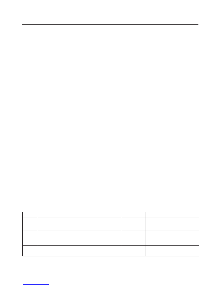
Engine Cranks But Will Not Run
Step
Action
Value(s)
Yes
No
1
Was the “On-Board Diagnostic (OBD) System Check”
performed?
—
Go to
Step 2
Go to
OBD
System
Check
2
Check the 15 A ignition coil fuse, the 15 A engine
device fuse, and the 15A PCM fuse.
Was a fuse blown?
—
Go to
Step 3
Go to
Step 4
3
Check for a short to ground and replace the fuse.
Is the action complete?
—
Verify repair
—
6E2–88
RODEO 6VD1 3.2L ENGINE DRIVEABILITY AND EMISSIONS
Engine Cranks But Will Not Run
(Cont'd)
Step
No
Yes
Value(s)
Action
4
1. Ignition “OFF,” install a fuel pressure gauge at the
test fitting on the fuel supply line in the engine
compartment. (Use a shop cloth to absorb any fuel
leakage while making the connection.)
2. Ignition “ON,” observe the fuel pressure.
Is the fuel pressure within the specified values, and
does it hold steady?
285-375 kPa
(43-55 psi)
Go to
Step 6
Go to
Step 5
5
Is any fuel pressure indicated?
—
Go to
Fuel
System
Electrical Test
Go to
Fuel
System
Diagnosis
6
Install the switch box J 39021-2 at the injector test
connector and activate an injector.
Did the fuel pressure drop when the injector was
activated?
—
Go to
Step 7
Go to
Step 18
7
Install an injector test light at the #2 cylinder injector
harness connector (or install J 39021-65 test light to the
the injector test connector).
Does the light blink when the engine is cranked?
—
Go to
Step 8
Go to
Step 24
8
1. Ignition “OFF.”
2. Disconnect the 6-pin connector at the ignition coil.
3. With a test light to B+, probe each of the 6 exposed
ignition module pins, one at a time, while the engine
is cranked. (Use the gray narrow METRA–PAK
flexible female connector from the J-35616 kit to
make the pin accessible.)
Does the light flash at each pin when the engine is
cranked?
—
Go to
Step 12
Go to
Step 9
9
1. Remove the 5-pin connector at the ignition coil.
2. Ignition “ON.”
3. Use a test light at the harness connector to verify
that the module is being supplied with B+ and
ground.
Was a problem found?
—
Go to
Step 10
Go to
Step 11
10
Repair the open ignition feed circuit or ground circuit to
the ignition coil.
Is the action complete?
—
Verify repair
—
11
Repair the ignition module.
Is the action complete?
—
Verify repair
—
12
1. Reconnect the ignition coil connector.
2. Remove the electrical connector from each coil.
3. With a test light to B+, probe each of the coil
connectors at the wire which runs to the ignition
module. (Wire color will match the wire color at the
ignition module 6-pin connector – green, or green
with a tracer.)
Does the light flash at each coil connector when the
engine is cranked?
—
Go to
Step 14
Go to
Step 13
13
Check for an open circuit between the ignition coil.
Is the action complete?
—
Verify repair
—
6E2–89
RODEO 6VD1 3.2L ENGINE DRIVEABILITY AND EMISSIONS
Engine Cranks But Will Not Run
(Cont'd)
Step
No
Yes
Value(s)
Action
14
1. Ignition “ON.”
2. While the coil connectors are disconnected, touch
each coil connector’s ignition feed terminal with a
grounded test light (the ignition feed wire is black
with orange tracer).
Did the test light illuminate?
—
Go to
Step 16
Go to
Step 15
15
Repair the open ignition feed circuit.
Is the action complete?
—
Verify repair
—
16
While the coil connectors are disconnected, touch
each connector’s secondary ground terminal with a
test light to B+. (The ground wires are black.)
Did the test light illuminate at each coil connector?
—
Go to
Step 18
Go to
Step 17
17
Repair the open secondary ground circuit.
Is the action complete?
—
Verify repair
—
18
1. Test the fuel for contamination.
2. If a problem is found, clean the fuel system and
correct the contaminated fuel condition as
necessary. Replace the fuel filter and replace any
injectors that are not delivering fuel (see Injector
Balance Test).
Was a problem found?
—
Verify repair
Go to
Step 19
19
1. Remove any ignition coil and install a spark tester at
the spark plug end of the coil.
2. Observe the tester while the engine is cranking.
Was a crisp, blue spark observed? Only one or two
sparks followed by no result is considered the same as
“No Spark.”
—
Go to
Step 21
Go to
Step 20
20
Replace the ignition coil, and return to Step 19 to test
the remaining coils.
Is the action complete?
—
Verify repair
—
21
Repeat Step 19 for each coil. Remove only one coil at a
time, and reinstall each coil on its spark plug after
testing, but do not refasten coils with screws at this
time.
After all coils have passed the spark test, does the
engine start?
—
Refasten all
coils with
their screws
Go to
Step 22
22
1. Remove the spark plugs from all cylinders.
2. Visually inspect the spark plug electrodes.
3. Replace any spark plugs with loose or missing
electrodes or cracked insulators.
Did your inspection reveal any spark plugs exhibiting
excessive fouling?
—
Correct the
fouling
condition
Go to
Step 23
6E2–90
RODEO 6VD1 3.2L ENGINE DRIVEABILITY AND EMISSIONS
Engine Cranks But Will Not Run
(Cont'd)
Step
No
Yes
Value(s)
Action
23
Refer to
Engine Mechanical Diagnosis to diagnose the
following conditions:
f
Faulty or incorrect camshaft drive belts
f
Leaking or sticky valves or rings
f
Excessive valve deposits
f
Loose or worn rocker arms
f
Weak valve springs
f
Incorrect valve timing
f
Leaking head gasket
Is the action complete?
—
Verify repair
Go to
Step 25
24
Observe the “Engine Speed” data display on the Tech 2
while cranking the engine.
Is the engine RPM indicated?
—
Go to
Step 25
Go to
Step 34
25
1. Disconnect the 7-pin gray connector at the rear of
the air filter beneath the point where the air duct
attaches to the MAF sensor.
2. Ignition “ON.”
3. Using a test light connected to ground, probe the
ignition terminal at the PCM (female) side of the
7-pin connector.
Is the test light “ON?”
—
Go to
Step 26
Go to
Step 32
26
1. At the PCM (female) side of the connector
mentioned in step 25, connect a test light between
the ignition + terminal and one of the injector driver
circuits at the same connector.
2. Ignition “ON.”
3. Observe the test light, and repeat the test for each
injector driver circuit.
Did the test light stay on when checking any of the 6
injector driver circuits?
—
Go to
Step 27
Go to
Step 29
27
1. Ignition “OFF,” disconnect the PCM.
2. Ignition “ON,” observe the test light.
Is the test light “ON?”
—
Go to
Step 28
Go to
Step 33
28
Locate and repair the short to ground in the injector
driver circuit.
Is the action complete?
—
Verify repair
—
29
1. Using the same test location as in step 26, connect
a test light between the ignition terminal and one of
the driver circuits.
2. Crank the engine and observe the test light.
3. Repeat for each injector driver circuit.
Did the light blink during the test for each circuit?
—
Go to
Step 31
Go to
Step 30
30
Check for an open injector driver circuit.
Was a problem found?
—
Verify repair
Go to
Step 33
Нет комментариевНе стесняйтесь поделиться с нами вашим ценным мнением.
Текст