Isuzu Rodeo UE. Manual — part 523
CLUTCH
7C–15
201RS009
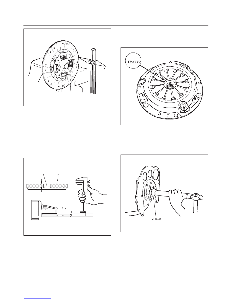
Rivet Head Depression
Use a depth gauge or a straight edge with steel rule to
measure the rivet head depression (1) from the facing
surface (2).
Be sure to measure the rivet head depression on both
sides of the driven plate. If the measured value is less
than the specified limit, the facing must be replaced.
Rivet Head Depression
Standard: MIN 1.3 mm (0.051 in)
Limit: 0.2 mm (0.008 in)
201RS010
Pressure Plate Assembly
Check the cover for cracks and distortion, and the
diaphragm spring for heat distortion, loosened rivets.
Check the diaphragm spring for wear.
201RS047
Installation
1. Clean and lubricate with grease.
2. Use installer J–1522 to install crankshaft bearing (6).
X22SE
015RS078
7C–16
CLUTCH
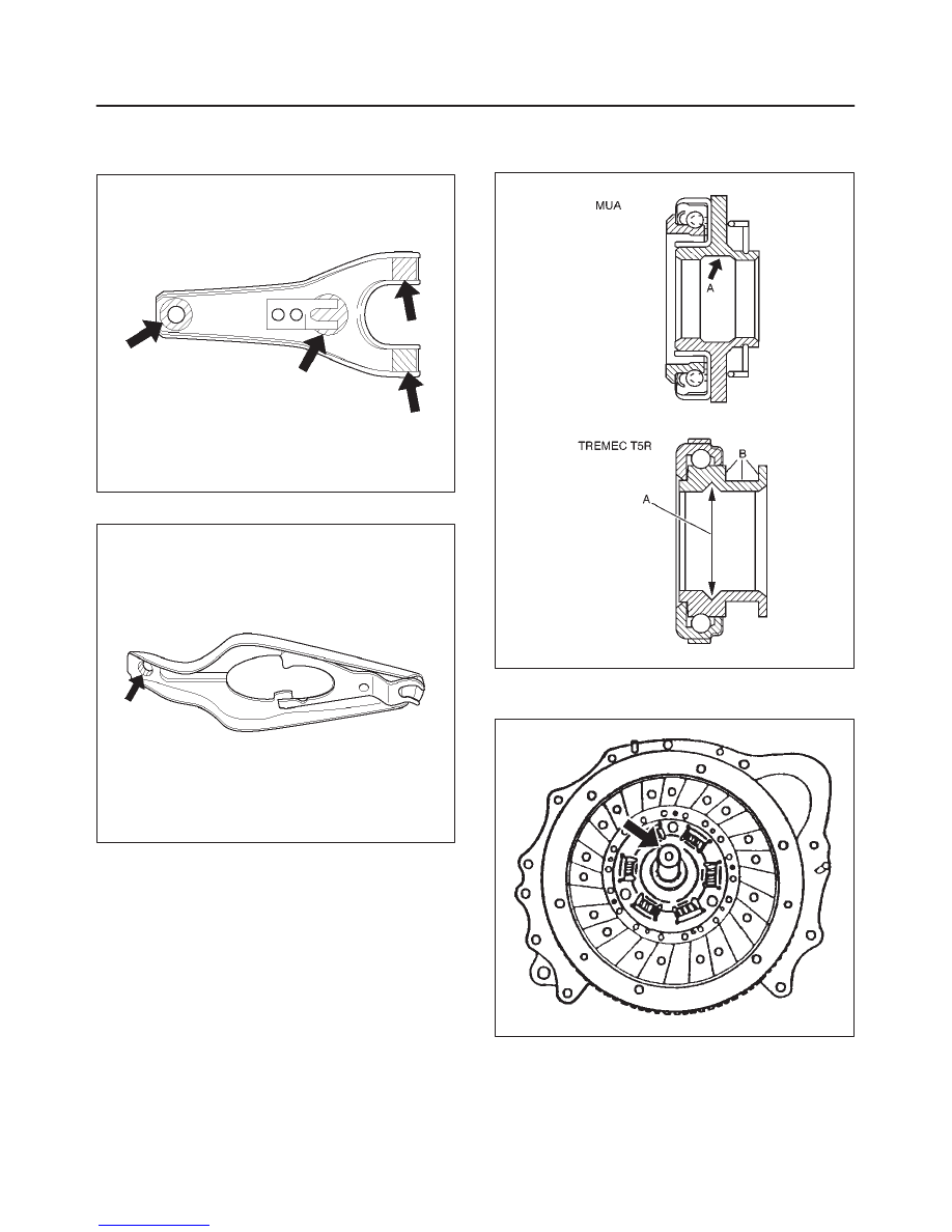
3. Apply molybdenum disulfide type grease to the areas
as shown in the figure and install shift fork (5).
MUA
F07RW030
TREMEC T5R
F07RW031
4. Pack the inside recess (A) and coat the outside
groove (B) of the release bearing with grease as
shown in the figure.
A07RX001
5. Install driven plate assembly by using aligner
J–33169 (TREMEC) / J–42877 (MUA).
201RS049
CLUTCH
7C–17
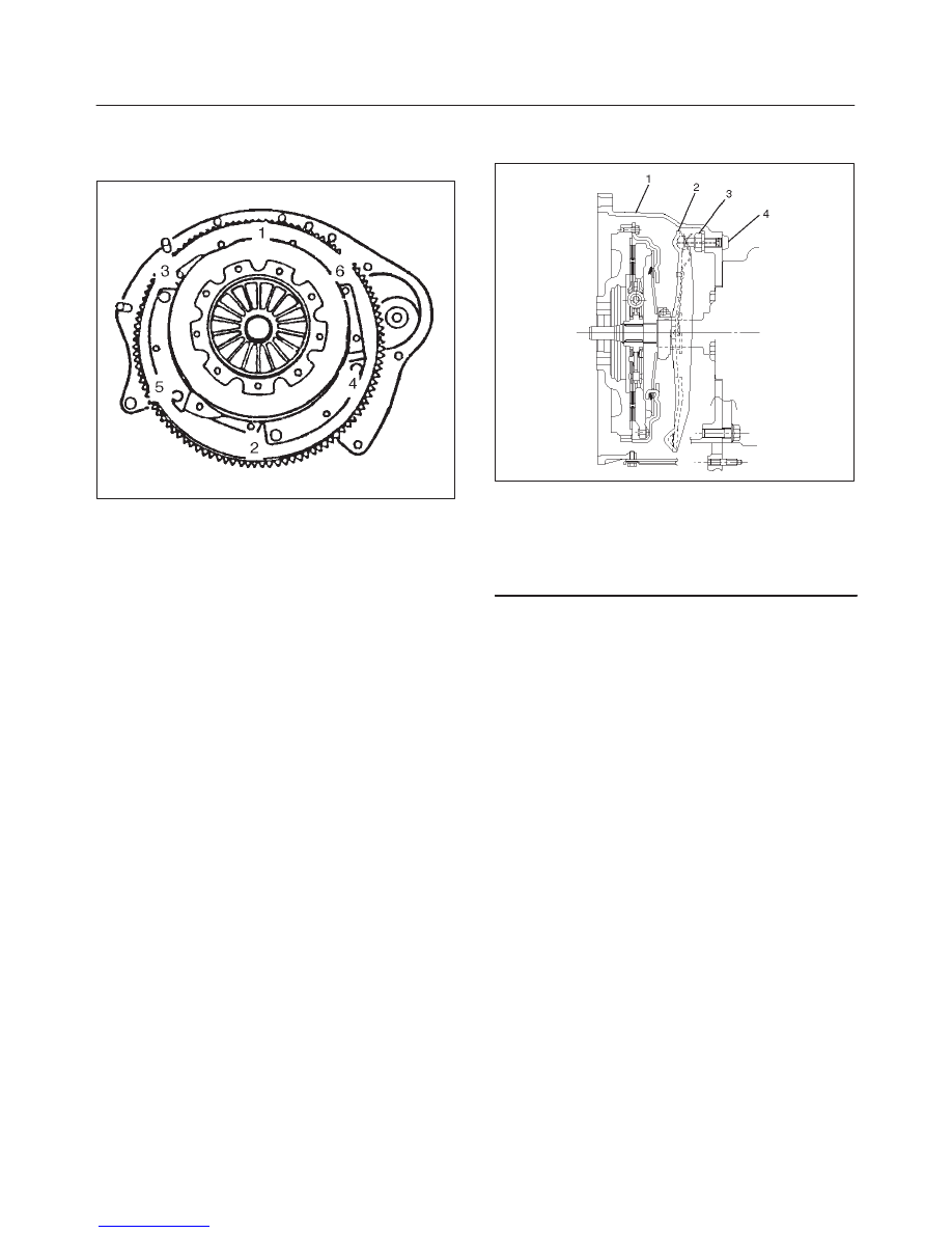
6. Tighten the bolts holding the pressure plate assembly
(2) in the order shown in the figure.
Torque: 18N·m (13 lb ft)
201RS050
7. Remove the aligner.
NOTE: Do not strike the aligner with a hammer to remove
it.
8. Install transmission assembly (1) to the engine. Refer
to Transmission Installation in Manual Transmission
section.
Shift Fork Lubrication
TREMEC T5R
201RW013
Legend
(1) Clutch Housing
(2) Shift Fork
(3) Ball Stud
(4) Plug
1. Remove the plug from the clutch housing.
2. Lubricate the shift fork through a lubrication hole of
ball stud with grease using a grease gun.
3. Install the plug to the clutch housing.
7C–18
CLUTCH
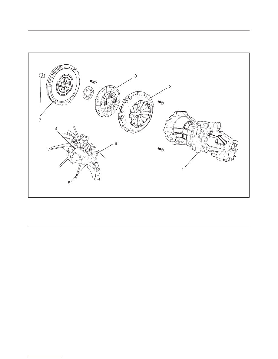
Clutch Assembly (6VD1, MUA)
Clutch Assembly (6VD1, MUA) and Associated Parts
201RS023
Legend
(1) Transmission Assembly
(2) Pressure Plate Assembly
(3) Driven Plate Assembly
(4) Release Bearing
(5) Shift Fork
(6) Fulcrum Bridge
(7) Flywheel Assembly and Crankshaft Bearing
Removal
1. Refer to “MANUAL TRANSMISSION” of Section 7B
for “REMOVAL AND INSTALLATION” procedure of
transmission assembly (1).
Нет комментариевНе стесняйтесь поделиться с нами вашим ценным мнением.
Текст