Isuzu Rodeo UE. Manual — part 522
CLUTCH
7C–11
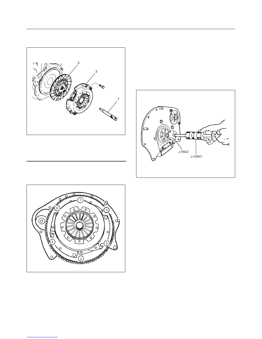
2. Use the clutch pilot aligner (7) J–33169 (TREMEC) /
J–42877 (MUA) to prevent the driven plate assembly
from falling free.
201RX002
Legend
(3) Driven Plate Assembly
(2) Pressure Plate Assembly
(7) Pilot Aligner
3. Mark the flywheel, clutch cover and pressure plate (2)
lug for alignment when installing.
4. Loosen the clutch cover bolts in the numerical order
shown in the illustration.
201RS036
5. Remove pressure plate assembly (2) and driven plate
assembly (3).
6. Remove release bearing (4).
NOTE: The release bearing is permanently packed with
lubricant and should not be soaked in cleaning solvent, as
this will dissolve the lubricant.
7. Remove shift fork.
f
Do not remove crank shaft bearing (6) except for
replacement.
Remove the crank shaft bearing (6) using remover
J–5822 and sliding hammer J–23907.
015RS077
Inspection and Repair
Make necessary adjustments, repairs, and part
replacements if wear, damage, or other problems are
discovered during inspection.
Pressure Plate Assembly
Visually inspect the pressure plate friction surface for
excessive wear and heat cracks. If excessive wear or
deep heat cracks are present, the pressure plate must be
replaced.
7C–12
CLUTCH
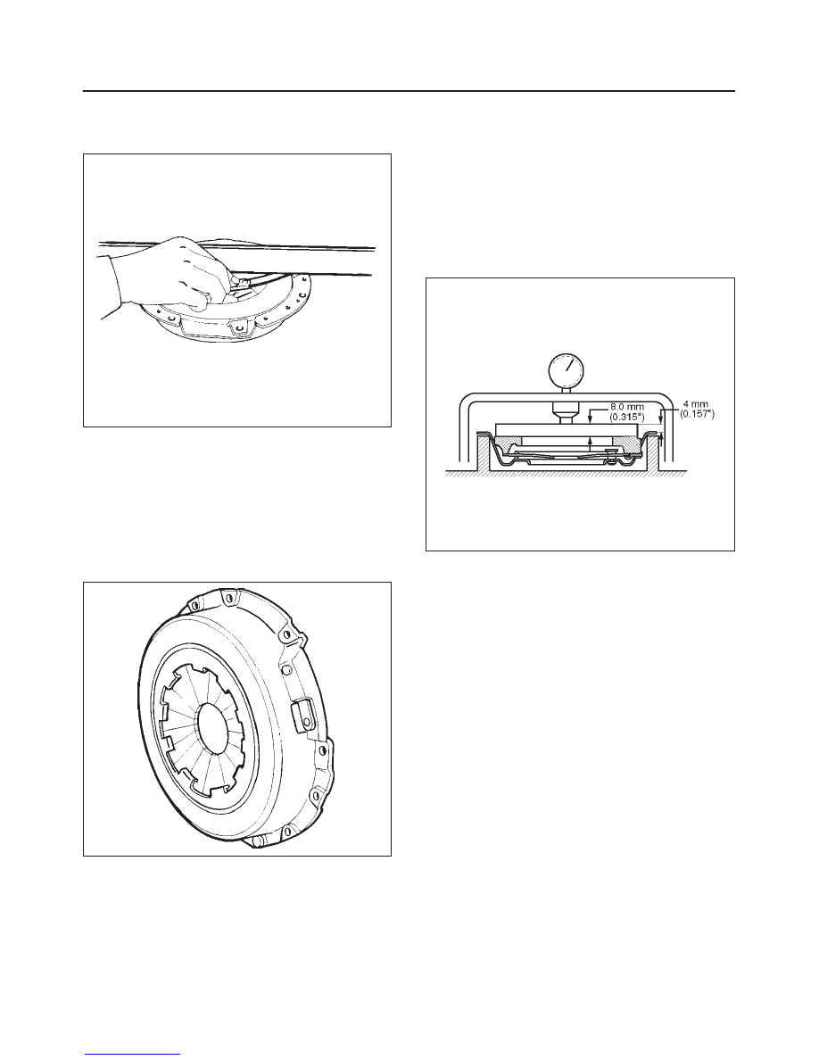
Pressure Plate Warpage
Use a straight edge and a feeler gauge to measure the
pressure plate friction surface flatness in four directions.
201RS038
If any of the measured values exceed the specified limit,
the pressure plate must be replaced.
Pressure Plate Warpage
Limit: 0.3mm (0.012in)
Clutch Cover
Visually inspect the entire clutch cover for excessive
wear, cracking, and other damage. The clutch cover must
be replaced if any of these conditions are present.
201RS039
Clutch Set Force
1. Invert the pressure plate assembly.
2. Place a new driven plate over the pressure plate. A
metal sheet with thickness of 8.0mm (0.315in) may
be used in place of the driven plate.
3. Compress the pressure plate assembly until the
distance becomes 4mm (0.157in).
4. Note the pressure gauge reading.
Clutch Set Force
Standard: 5488N (1235lb)
201RW015
CLUTCH
7C–13
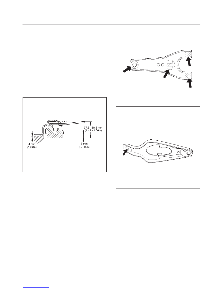
Diaphragm Spring Finger Height
1. Place a 8.0mm (0.315in) spacer beneath the
pressure plate.
2. Fully compress the pressure plate and diaphragm
spring.
There are two ways to do this:
a. Use a bench press to press down on the assembly
from the top.
b. Tighten the fixing bolts.
3. Measure the spring finger height from base to spring
tip.
If the measured value exceeds the specified limit, the
pressure plate assembly must be replaced.
Spring Finger Height
Standard: 37.5 mm – 39.5 mm (1.48 in – 1.56 in)
A07RX002
Shift Fork
1. Visually inspect the surfaces of the shift fork making
contact with the shift block.
2. Remove any minor stepping or abrasion from the shift
block with an oil stone.
3. Apply molybdenum disulfide type grease to the areas
as shown in the figure.
MUA
F07RW030
TREMEC T5R
F07RW031
7C–14
CLUTCH
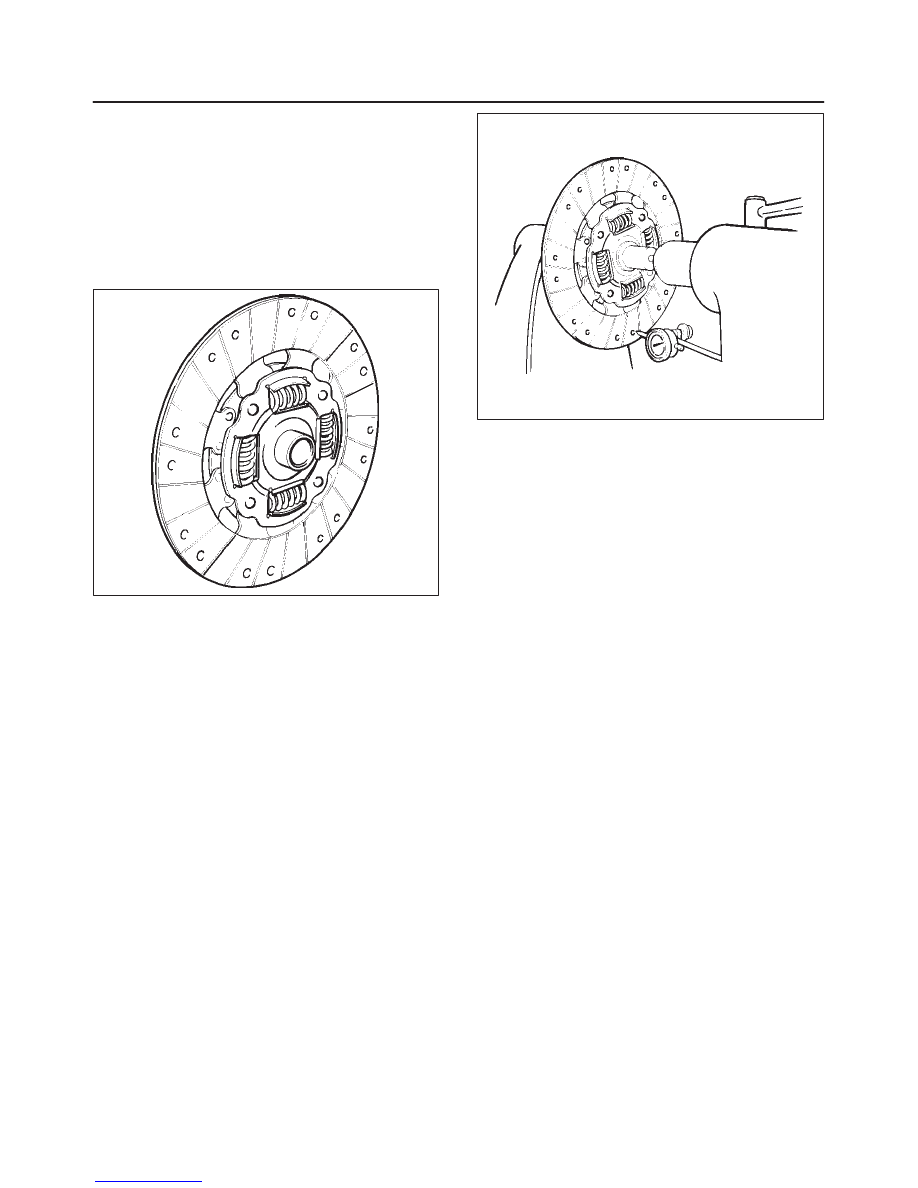
Driven Plate Assembly
1. Visually inspect the torsion spring for looseness,
breakage, and weakening. If any of these conditions
are discovered, the driven plate assembly must be
replaced.
2. Visually inspect the facing surfaces for cracking and
excessive scorching. Visually inspect the facing
surfaces for the presence of oil or grease. If any of
these conditions are discovered, the facing must be
cleaned or replaced.
201RS007
3. Check that the driven plate moves smoothly on the
transmission top gear shaft spline.
Minor ridges on the top gear shaft spline may be
removed with an oil stone.
Driven Plate Warpage
1. Insert the clutch pilot aligner J–33169 (TREMEC) /
J–42877 (MUA) into the driven plate splined hub.
The clutch pilot aligner must be held perfectly
horizontal.
2. Set a dial indicator to the driven plate outside
circumference.
201RS008
3. Slowly turn the driven plate. Read the dial indicator as
you turn the driven plate.
If the measured value exceeds the specified limit, the
driven plate assembly must be replaced.
Driven Plate Warpage
Standard: 0.7 mm (0.028 in)
Limit: 1.0 mm (0.039 in)
Driven Plate Splined Hub Spline Wear
1. Clean the driven plate splined hub.
2. Install the driven plate to the transmission top gear
shaft spline.
3. Set a surface gauge to the driven plate outside
circumference.
4. Slowly turn the driven plate counterclockwise.
Measure the spline rotation play as you turn the
driven plate.
Driven Plate Splined Hub Spline Wear
Standard: 0.5 mm (0.020 in)
Limit: 1.0 mm (0.039 in)
Нет комментариевНе стесняйтесь поделиться с нами вашим ценным мнением.
Текст