Isuzu Rodeo UE. Manual — part 12
1A–18 HEATING, VENTILATION AND AIR CONDITIONING (HVAC)
Installation
To install, follow the removal steps in the reverse order,
noting the following points:
1. Apply grease to the sub-lever and to the abrasive
surface of the heater unit.
2. After installing the link unit, check to see if the link unit
operates correctly.
Blower Assembly
Blower Assembly and Associated Parts
873RW004
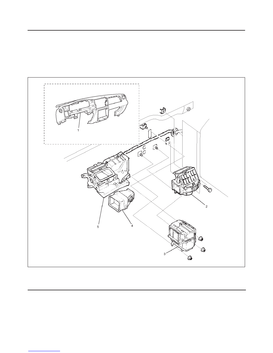
Legend
(1) Instrument Panel Assembly
(2) Blower Assembly
(3) Evaporator Assembly (A/C only)
(4) Duct
(5) Heater Unit
Removal
1. Disconnect the battery ground cable.
2. Discharge and recover refrigerant (with air
conditioning).
f
Refer to Refrigerant Recovery in this section.
3. Remove instrument panel assembly.
f
Refer to Instrument Panel Assembly in Body and
Accessories section.
4. Disconnect resistor connector.
5. Remove duct.

HEATING, VENTILATION AND AIR CONDITIONING (HVAC) 1A–19
6. Remove evaporator assembly (A/C only).
f
Refer to Evaporator Assembly in this section.
7. Disconnect blower motor connector.
8. Remove blower assembly.
Installation
To install, follow the removal steps in the reverse order,
noting the following point:
1. Adjust the control cables.
f
Refer to Control Lever Assembly in this section.
Blower Link Unit and / or Mode door
Disassembled View
873RS001
Legend
(1) Upper Case
(2) Mode Door
(3) Lower Case
(4) Sub Lever
(5) Door Lever
(6) Blower Assembly
Removal
1. Disconnect the battery ground cable.
2. Discharge and recover refrigerant (with air
conditioning).
f
Refer to Refrigerant Recovery in this section.
3. Remove blower assembly.
f
Refer to Blower Assembly in this section.
4. Remove lower case.
1A–20 HEATING, VENTILATION AND AIR CONDITIONING (HVAC)
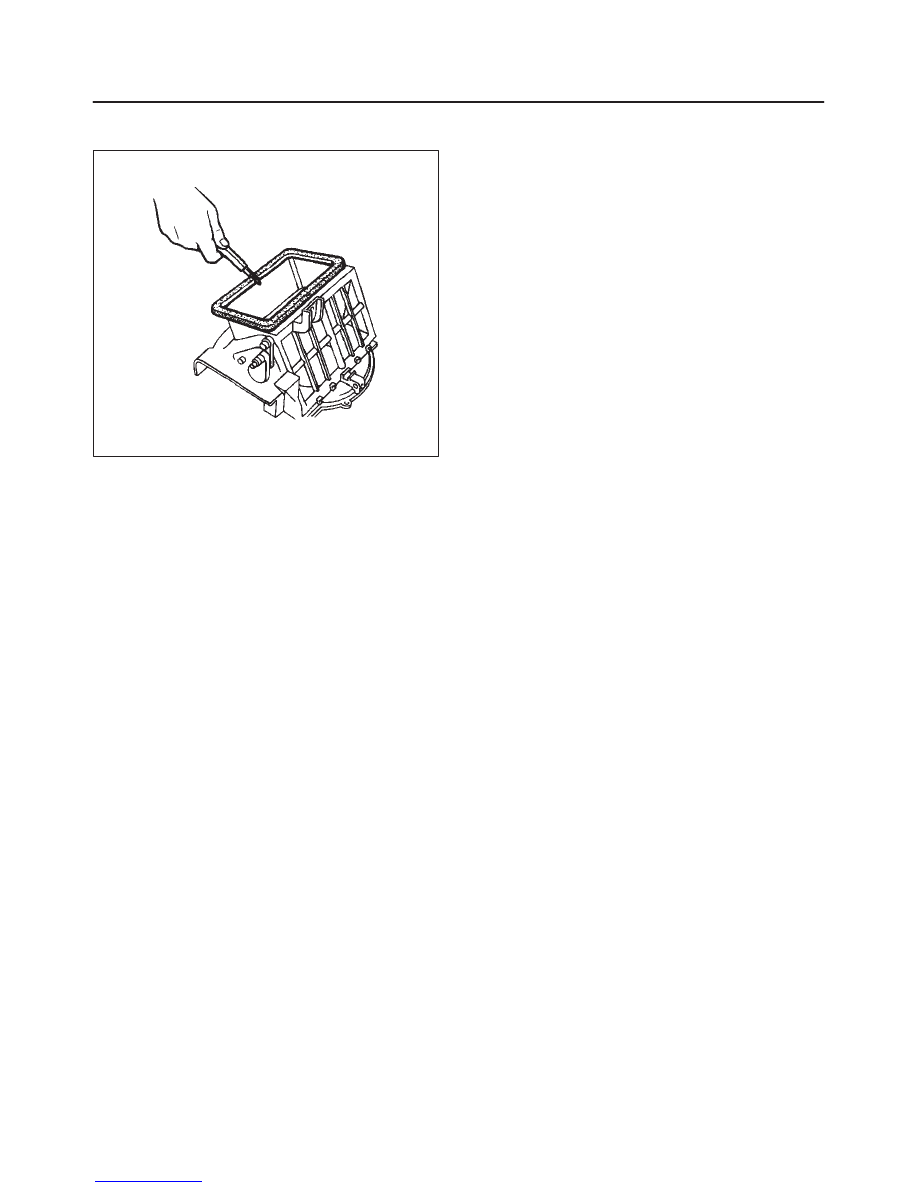
5. Separate the upper case and slit the lining parting
face with a knife.
873RS002
6. Pull out the mode door while raising up the catch of
door lever.
7. Remove sub-lever.
8. Remove door lever.
Installation
To install, follow the removal steps in the reverse order,
noting the following points:
1. Apply grease to the door lever and to the abrasive
surface of the upper case.
2. Apply an adhesive to the parting face of the lining
when assembling the upper case.
HEATING, VENTILATION AND AIR CONDITIONING (HVAC) 1A–21
Blower Motor
Blower Motor and Associated Parts
873RW001
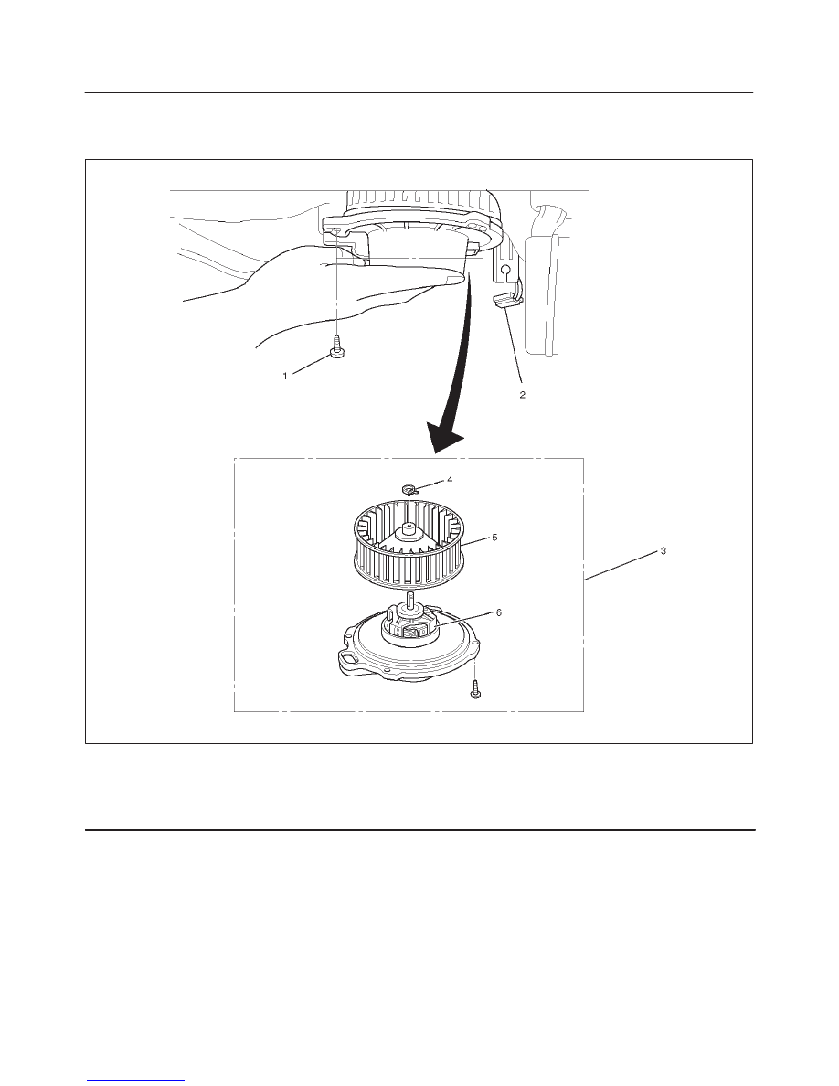
Legend
(1) Attaching Screw
(2) Blower Motor Connector
(3) Blower Motor Assembly
(4) Clip
(5) Fan
(6) Blower Motor
Removal
1. Disconnect the battery ground cable.
2. Remove blower motor connector.
3. Remove attaching screw.
4. Remove blower motor assembly.
5. Remove clip.
6. Remove fan.
7. Remove blower motor.
Installation
To install, follow the removal steps in the reverse order.
Нет комментариевНе стесняйтесь поделиться с нами вашим ценным мнением.
Текст