Isuzu Rodeo UE. Manual — part 11
1A–14 HEATING, VENTILATION AND AIR CONDITIONING (HVAC)
Installation
To install, follow the removal steps in the reverse order,
noting the following points:
1. When handling the PCM and the control unit, be
careful not to make any improper connection of the
connectors.
2. Adjust the control cables.
f
Refer to Control Lever Assembly in this section.
3. When installing the heater unit, defroster nozzle and
center vent duct, be sure that the proper seal is made,
without any gap between them.
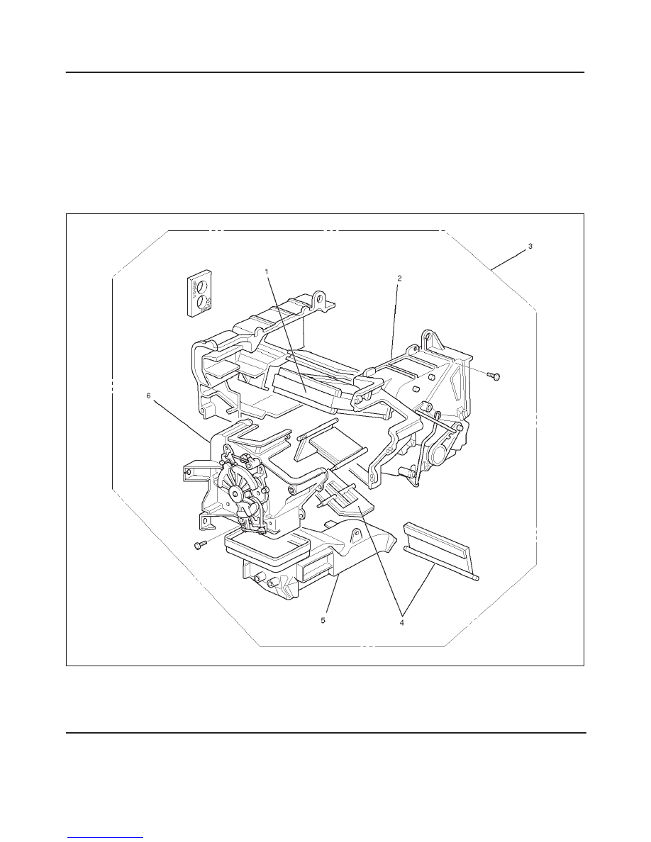
Heater Core and / or Mode Door
Disassembled View
860RW001
Legend
(1) Heater Core
(2) Case (Temperature Control)
(3) Heater Unit
(4) Mode Door
(5) Duct
(6) Case (Mode Control)
Removal
1. Disconnect the battery ground cable.
2. Drain the engine coolant.
3. Discharge and recover refrigerant (with air
conditioning).
f
Refer to Refrigerant Recovery in this section.
HEATING, VENTILATION AND AIR CONDITIONING (HVAC) 1A–15
4. Remove heater unit.
f
Refer to Heater Unit in this section.
5. Remove duct.
6. Remove case (Mode control) and do not remove link
unit at this step.
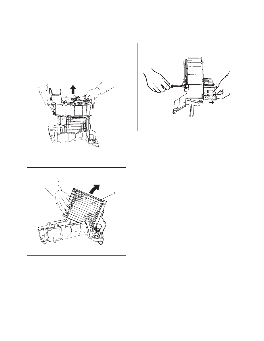
7. Remove case (Temperature control) separate two
halves of core case.
860RS002
8. Remove heater core (1).
860RS003
9. Pull out the mode door while raising up the catch of
the door lever.
860RS004
Inspection
Check for foreign matter in the heater core, stain or the
core fin defacement.
Installation
To install, follow the removal steps in the reverse order,
noting the following point:
1. Check that each mode door operates properly.
1A–16 HEATING, VENTILATION AND AIR CONDITIONING (HVAC)
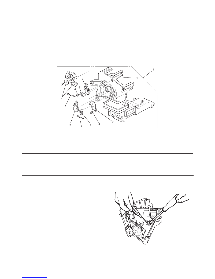
Heater Mode Control Link Unit
Disassembled View
860RW002
Legend
(1) Case (Mode Control)
(2) Heater Unit
(3) Mode Sub-lever
(4) Clip
(5) Door Lever
(6) Rod
(7) Washer and Mode Main Lever
Removal
1. Disconnect the battery ground cable.
2. Drain engine coolant.
3. Discharge and recover refrigerant (with air
conditioning)
f
Refer to Refrigerant Recovery in this section.
4. Remove heater unit.
f
Refer to Heater Unit in this section.
5. Remove the case (Mode control) from heater unit.
6. Remove washer and the mode main lever.
7. Remove rod.
8. Press the tab of the sub-lever inward, and take out the
sub-lever.
860RS006

HEATING, VENTILATION AND AIR CONDITIONING (HVAC) 1A–17
9. Pull out the door lever while raising up the catch of the
door lever.
10. Remove clip.
Installation
To install, follow the remove steps in the reverse order,
noting the following points:
1. Apply grease to the mode sub-lever and to the
abrasive surface of the heater unit.
2. After installing the link unit, check to see if the link unit
operates correctly.
Heater Temperature Control Link Unit
Disassembled View
860RS007
Legend
(1) Case (Temperature control)
(2) Clip
(3) Door Lever
(4) Clip
(5) Heater Unit
(6) Rod
(7) Sub-lever
Removal
1. Disconnect the battery ground cable.
2. Drain engine coolant.
3. Discharge and recover refrigerant (with air
conditioning).
f
Refer to Refrigerant Recovery in this section.
4. Remove heater unit.
f
Refer to Heater Unit in this section.
5. Remove the case (Temperature control) from the
heater unit.
6. Remove rod.
7. Remove sub-lever.
8. Pull out the door lever while raising up the catch of the
door lever.
9. Remove clip.
Нет комментариевНе стесняйтесь поделиться с нами вашим ценным мнением.
Текст