Isuzu Rodeo UE. Manual — part 562
8D–96
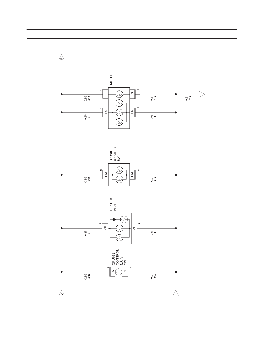
WIRING SYSTEM
Circuit Diagram–3
D08RW041
8D–97
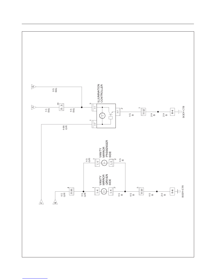
WIRING SYSTEM
Circuit Diagram–4
D08RW042
8D–98
WIRING SYSTEM
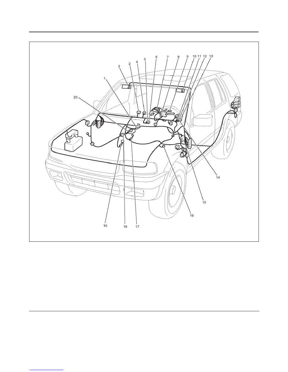
Parts Location
D08RW106
Legend
(1) I–33
(2) L–5
(3) I–11
(4) I–27
(5) I–17
(6) I–16
(7) I–1
(8) I–2
(9) I–9
(10) L–4
(11) I–5
(12) I–6
(13) I–19
(14) I–7
(15) I–32, I–34
(16) B–8
(17) I–15
(18) H–25
(19) I–40
(20) B–24
8D–99
WIRING SYSTEM
Turn Signal Light, Hazard Warning Light
General Description
The circuit consists of turn signal/cornering switch
(combination switch) turn signal light, hazard warning
switch and flasher unit. When turn signal light switch is
turned on with starter switch on, turn signal light will
operate. When turn signal light is flashing, indicator light
in meter also starts flashing. When hazard warning switch
is turned on, current flows to flasher unit through hazard
warning switch to cause hazard warning light to flash
independent of position of starter switch. At the same
time, indicator lights in meter also start flashing.
When turn signal lever is set in either left or right direction
while headlight is on, incorporated into combination
switch is activated to illuminated.
Нет комментариевНе стесняйтесь поделиться с нами вашим ценным мнением.
Текст