Isuzu Rodeo UE. Manual — part 560
8D–88
WIRING SYSTEM
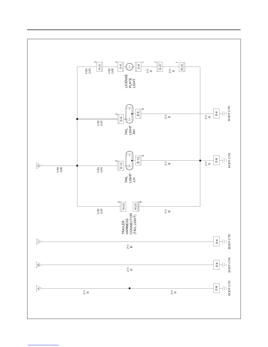
Circuit Diagram–2
D08RW013
8D–89
WIRING SYSTEM
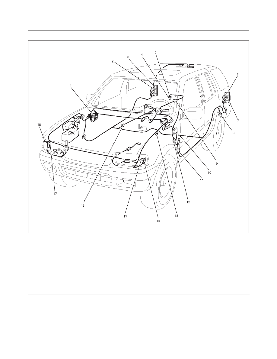
Parts Location
D08RW108
Legend
(1) H–19
(2) B–9
(3) Tail Light – RH
(4) License Plate Light
(5) G–8
(6) Tail Light – LH
(7) B–13
(8) H–23
(9) H–27
(10) I–32, I–34
(11) H–32
(12) H–30
(13) B–6, B–8
(14) C–23
(15) FRT Combination Light – LH
(16) H–25
(17) C–31
(18) FRT Combination Light – RH

8D–90
WIRING SYSTEM
Diagnosis
Both Tail Lights Inoperative
Step
Action
Value(s)
Yes
No
1
Is fuse (15A) normal?
—
Go to Step 2
Replace the
fuse
2
Is the tail relay normal?
—
Go to Step 3
Replace the
tail relay
3
Is B-8 terminal ground securely?
—
Go to Step 4
Ground B-8
terminal
securely
4
Remove the connector of the lighting switch.
Is there continuity between I-32 terminals 3 and 2 when
the switch is turned to parking or headlight position?
—
Go to Step 5
Repair or
replace the
lighting switch
5
Is the battery voltage applied between the harness side
connectors I-32 terminal 3 and the ground?
—
Go to Step 6
Repair a poor
connection at
the
connectors or
an open
circuit
between fuse
(15A) and
I-32 terminal
3
6
Repair a poor connection at the connectors or an open
circuit between I-34 terminal 1 and H-25 terminal 14 or
B-13 terminal 4 (B-9 terminal 4 and B-8 terminal)
Is the action complete?
—
Verify repair
—
Tail Light On The Left (or Right) Side Inoperative
Step
Action
Value(s)
Yes
No
1
Is the taillight bulb on the left (or right) side normal?
—
Go to Step 2
Replace the
bulb
2
Is there continuity between H-25 terminal 14 and B-13
terminal 13 (B-9 terminal 3)?
—
—
Repair a poor
connection of
the
connectors or
an open
circuit in the
circuit.
3
Repair a poor connection of the connectors or an open
circuit between B-13 terminal 4 (B-9 terminal 4) and B-8
terminal.
Is the action complete?
—
Verify repair
—
NOTE: Connectors in parenthesis “( )” indicates the
check point of the taillight on the right side.

8D–91
WIRING SYSTEM
Both Front Side Marker Lights Inoperative
Step
Action
Value(s)
Yes
No
1
Is fuse (15A) normal?
—
Go to Step 2
Replace the
fuse
2
Is the tail relay normal?
—
Go to Step 3
Replace the
tail relay
3
Is B-8 terminal (B-6 terminal) grounded securely?
—
Go to Step 4
Ground B-8
terminal (B-6
terminal)
terminal
securely
4
Remove the connector of the lighting switch.
Is there any continuity between I-32 terminals and 2
when the switch is turned to parking or headlight
position?
—
Go to Step 5
Repair or
replace the
lighting switch
5
Is the battery voltage applied between the harness side
connector I-32 terminal 3 and the ground?
—
Go to Step 6
Repair a poor
connection at
the
connectors or
an open
circuit
between fuse
I-34 terminal
3 and I-32
terminal 3
6
Repair a poor connection at the connectors or an open
circuit between I-34 terminal 1 and H-19 terminal 6, or
B-8 terminal and ( I-31 terminal 4 and B-6 terminal).
Is the action complete?
—
Verify repair
—
Front Side Marker Light On The Left (or Right) Side Inoperative
Step
Action
Value(s)
Yes
No
1
Is the front side marker light bulb on the left (or right)
side normal?
—
Go to Step 2
Replace the
bulb
2
Is there continuity between H-19 terminal 6 and C-32
terminal 3 (C-31 terminal 3)?
—
Go to Step 3
Repair a poor
connection at
the
connectors or
an open
circuit in the
circuit
3
Repair a poor connection at the connectors or an open
circuit between C-23 terminal (C-31 terminal 4) and B-8
terminal (B-6 terminal).
Is the action complete?
—
Verify repair
—
NOTE: Connectors in parenthesis “( )” indicates the
check point of the taillight on the right side.
Нет комментариевНе стесняйтесь поделиться с нами вашим ценным мнением.
Текст