Isuzu Rodeo UE. Manual — part 94
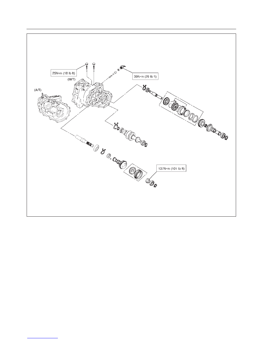
TRANSFER CASE
4D–39
E07RX005
4D–40
TRANSFER CASE
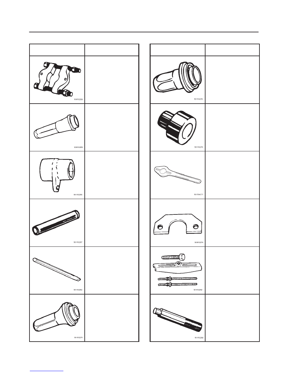
Special Tools
ILLUSTRATION
PART NO.
PART NAME
J–22912–01
Bearing
remover/installer
J–38592
Transfer case oil seal
installer
J–37219
Mainshaft nut wrench
J–37223
Rear output shaft and
bearing installer
J–39209
Punch; end nut
J–38594
Front output shaft oil
seal installer
ILLUSTRATION
PART NO.
PART NAME
J–39208
Rear oil seal installer
J–37486–A
Bearing installer adapter
J–8614–11
Flange holder
J–37217
Mainshaft end bearing
remover
J–37487
Puller
J–8092
Driver handle
5A–1
BRAKE CONTROL SYSTEM
RODEO
BRAKES
CONTENTS
Brake Control System
5A–1
. . . . . . . . . . . . . . . . . . . .
Anti–lock Brake System
5B–1
. . . . . . . . . . . . . . . . . .
Power–assisted Brake System
5C–1
. . . . . . . . . . . .
Parking Brakes (4x4 Model)
5D1–1
. . . . . . . . . . . . . .
Parking Brakes (4x2 Model)
5D2–1
. . . . . . . . . . . . . .
Brake Control System
CONTENTS
Service Precaution
5A–2
. . . . . . . . . . . . . . . . . . . . . .
General Description
5A–3
. . . . . . . . . . . . . . . . . . . . .
Functional Description
5A–4
. . . . . . . . . . . . . . . . .
System Components
5A–10
. . . . . . . . . . . . . . . . . . .
Electronic Hydraulic Control Unit (EHCU)
5A–10
.
ABS Warning Light
5A–10
. . . . . . . . . . . . . . . . . . . .
Wheel Speed Sensor
5A–10
. . . . . . . . . . . . . . . . . .
G-Sensor
5A–10
. . . . . . . . . . . . . . . . . . . . . . . . . . . . .
Normal and Anti-lock Braking
5A–10
. . . . . . . . . . .
Brake Pedal Travel
5A–10
. . . . . . . . . . . . . . . . . . . .
Acronyms and Abbreviations
5A–10
. . . . . . . . . . . .
General Diagnosis
5A–11
. . . . . . . . . . . . . . . . . . . . . . .
General Information
5A–11
. . . . . . . . . . . . . . . . . . . .
ABS Service Precautions
5A–11
. . . . . . . . . . . . . . .
Computer System Service Precautions
5A–11
. . .
General Service Precautions
5A–11
. . . . . . . . . . . .
Note on Intermittents
5A–11
. . . . . . . . . . . . . . . . . . .
Test Driving ABS Complaint Vehicles
5A–12
. . . . .
“ABS” Warning Light
5A–12
. . . . . . . . . . . . . . . . . . .
Normal Operation
5A–12
. . . . . . . . . . . . . . . . . . . . .
Tech 2 Scan Tool
5A–13
. . . . . . . . . . . . . . . . . . . . . .
DATA LIST
5A–16
. . . . . . . . . . . . . . . . . . . . . . . . . . .
ACTUATOR TEST
5A–17
. . . . . . . . . . . . . . . . . . . . .
Tech 2 Service Bleed
5A–21
. . . . . . . . . . . . . . . . . .
Basic Diagnostic Flow Chart
5A–22
. . . . . . . . . . . .
Basic Inspection Procedure
5A–23
. . . . . . . . . . . . .
EHCU Connector Pin-out Checks
5A–24
. . . . . . . . .
Circuit Diagram
5A–25
. . . . . . . . . . . . . . . . . . . . . . .
Connector List
5A–28
. . . . . . . . . . . . . . . . . . . . . . . .
Part Location
5A–29
. . . . . . . . . . . . . . . . . . . . . . . . .
Symptom Diagnosis
5A–30
. . . . . . . . . . . . . . . . . . . . .
Chart A-1 ABS Works Frequently But
Vehicle Does Not Decelerate
5A–30
. . . . . . . . . . .
Chart TA-1 ABS Works Frequently But
Vehicle Does Not Decelerate
(Use TECH 2)
5A–31
. . . . . . . . . . . . . . . . . . . . . . . .
Chart A-2 Uneven Braking Occurs While
ABS Works
5A–31
. . . . . . . . . . . . . . . . . . . . . . . . . . .
Chart TA-2 Uneven Braking Occurs While
ABS Works (Use TECH 2)
5A–31
. . . . . . . . . . . . .
Chart A-3, TA-3 The Wheels Are Locked
5A–32
.
Chart A-4 Brake Pedal Feed Is Abnormal
5A–33
.
Chart A-5, TA-5 Braking Sound
(From EHCU) Is Heard While Not Braking
5A–34
Diagnostic Trouble Codes
5A–35
. . . . . . . . . . . . . . . .
Diagnosis By “ABS” Warning Light
Illumination Pattern
5A–37
. . . . . . . . . . . . . . . . . . . . .
Diagnostic Trouble Codes (DTCs)
5A–38
. . . . . . .
Chart B-1 With the key in the ON position
(Before starting the engine). Warning
light (W/L) is not activated.
5A–40
. . . . . . . . . . . . .
Chart B-2 CPU Error (DTC 14 (Flash out) /
C0271, C0272, C0273, C0284 (Serial
communications))
5A–41
. . . . . . . . . . . . . . . . . . . . .
Chart B-3 Low or High Ignition Voltage
(DTC 15 (Flash out) / C0277, 0278
(Serial communications))
5A–41
. . . . . . . . . . . . . . .
Chart B-4 Excessive Dump Time
(DTC 17 (Flash out) / C0269
(Serial communications))
5A–41
. . . . . . . . . . . . . . .
Chart B-5 Excessive Isolation Time
(DTC 18 (Flash out) / C0274
(Serial communications))
5A–42
. . . . . . . . . . . . . . .
Chart B-6 G-Sensor Output Failure
(DTC 21 (Flash out) / C0276
(Serial communications))
5A–42
. . . . . . . . . . . . . . .
Chart B-7 Brake Switch Failure
(DTC 22 (Flash out) / C0281
(Serial communications))
5A–42
. . . . . . . . . . . . . . .
Chart B-8 2WD Controller in 4WD Vehicle
Controller (DTC 13 (Flash out) / C0285
(Serial communications)), 4WD State Input
Signal Failure (DTC 24 (Flash out) / C0282
(Serial communications))
5A–43
. . . . . . . . . . . . . . .
Chart B-9 Pump Motor Failure (DTC 32
(Flash out) / C0267, C0268
(Serial communications))
5A–43
. . . . . . . . . . . . . . .
Chart B-10 EHCU Valve Relay Failure
(DTC 35 (Flash out) / C0265, C0266
(Serial communications))
5A–44
. . . . . . . . . . . . . . .
Chart B-11 FL Isolation Solenoid Coil Failure
(DTC 41 (Flash out) / C0245, C0247
(Serial communications))
5A–44
. . . . . . . . . . . . . . .
Chart B-12 FL Dump Solenoid Coil Failure
(DTC 42 (Flash out) / C0246, C0248
(Serial communications))
5A–44
. . . . . . . . . . . . . . .
5A–2
BRAKE CONTROL SYSTEM
Chart B-13 FR Isolation Solenoid Coil Failure
(DTC 43 (Flash out) / C0241, C0243
(Serial communications))
5A–45
. . . . . . . . . . . . . . .
Chart B-14 FR Dump Solenoid Coil Failure
(DTC 44(Flash out) / C0242, C0244
(Serial communications))
5A–45
. . . . . . . . . . . . . . .
Chart B-15 Rear Isolation Solenoid Coil
Failure (DTC 45 (Flash out) / C0251,
C0253 (Serial communications))
5A–45
. . . . . . . .
Chart B-16 Rear Dump Solenoid Coil
Failure (DTC 46 (Flash out) / C0252,
C0254 (Serial communications))
5A–46
. . . . . . . .
Chart B-17 FL Speed Sensor Open or
Shorted (DTC 51 (Flash out) / C0225
(Serial communications))
5A–46
. . . . . . . . . . . . . . .
Chart B-18 FR Speed Sensor Open or
Shorted (DTC 52 (Flash out) / C0221
(Serial communications))
5A–47
. . . . . . . . . . . . . . .
Chart B-19 Rear Speed Sensor Open or
Shorted (DTC 53 (Flash out) / C0235
(Serial communications))
5A–48
. . . . . . . . . . . . . . .
Chart B-20 FL Speed Sensor Missing
(DTC 61 (Flash out) / C0226, C0227
(Serial communications))
5A–49
. . . . . . . . . . . . . . .
Chart B-21 FR Speed Sensor Missing
(DTC 62 (Flash out) / C0222, C0223
(Serial communications))
5A–50
. . . . . . . . . . . . . . .
Chart B-22 Rear Speed Sensor Missing
(DTC 63 (Flash out) / C0236, C0237
(Serial communications))
5A–51
. . . . . . . . . . . . . . .
Chart B-23 Simultaneous Drop-out of
Front Speed Sensor Signal (DTC 64 (Flash
out) / C0229 (Serial communications))
5A–52
. . .
Chart B-24 Wheel Speed Input Abnormality
(DTC 65 (Flash out) / C0238 (Serial
communications))
5A–53
. . . . . . . . . . . . . . . . . . . . .
Unit Inspection Procedure
5A–54
. . . . . . . . . . . . . . . .
Chart C-1-1 FL Sensor Output Inspection
Procedure
5A–54
. . . . . . . . . . . . . . . . . . . . . . . . . . .
Chart C-1-2 FR Sensor Output Inspection
Procedure
5A–55
. . . . . . . . . . . . . . . . . . . . . . . . . . .
Chart C-1-3 Rear Sensor Output Inspection
Procedure
5A–55
. . . . . . . . . . . . . . . . . . . . . . . . . . .
Chart TC-1 Sensor Output Inspection
Procedure
5A–56
. . . . . . . . . . . . . . . . . . . . . . . . . . .
Special Tools
5A–57
. . . . . . . . . . . . . . . . . . . . . . . . . . .
Service Precaution
WARNING: THIS VEHICLE HAS A SUPPLEMENTAL
RESTRAINT SYSTEM (SRS). REFER TO THE SRS
COMPONENT AND WIRING LOCATION VIEW IN
ORDER TO DETERMINE WHETHER YOU ARE
PERFORMING SERVICE ON OR NEAR THE SRS
COMPONENTS OR THE SRS WIRING. WHEN YOU
ARE PERFORMING SERVICE ON OR NEAR THE SRS
COMPONENTS OR THE SRS WIRING, REFER TO
THE SRS SERVICE INFORMATION. FAILURE TO
FOLLOW WARNINGS COULD RESULT IN POSSIBLE
AIR BAG DEPLOYMENT, PERSONAL INJURY, OR
OTHERWISE UNNEEDED SRS SYSTEM REPAIRS.
CAUTION: Always use the correct fastener in the
proper location. When you replace a fastener, use
ONLY the exact part number for that application.
ISUZU will call out those fasteners that require a
replacement after removal. ISUZU will also call out
the fasteners that require thread lockers or thread
sealant. UNLESS OTHERWISE SPECIFIED, do not
use supplemental coatings (Paints, greases, or other
corrosion inhibitors) on threaded fasteners or
fastener joint interfaces. Generally, such coatings
adversely affect the fastener torque and the joint
clamping force, and may damage the fastener. When
you install fasteners, use the correct tightening
sequence and specifications. Following these
instructions can help you avoid damage to parts and
systems.
Нет комментариевНе стесняйтесь поделиться с нами вашим ценным мнением.
Текст