Isuzu Rodeo UE. Manual — part 71

4B–15
DRIVELINE CONTROL SYSTEM
2. Case that indicator keeps 2Hz blinking after aforementioned Solution 3 is carried out.
Step
Action
Yes
No
1
Check the air pressure and wear of all tires.
Were problems found?
Try Solution 3
after adjust the
air pressure and
replace worn
tires.
Go to Step 2
2
Can the transfer lever be operated from High to 4L or vice versa?
Faults on the
harness wiring of
motor actuator.
Trace this chart
from the start
after repair or
replace.
Internal faults on
transfer case.
Disassemble the
transfer case for
check. Trace this
chart from the
start after repair
or replace.
Faults on the
motor actuator.
Trace this chart
from the start
after or replace.
Go to Step 3
3
Pull out the hoses from vacuum actuator and operate 4WD
switch.
Is there negative pressure on either of hoses?
Go to Step 4
Faults on the
transfer position
switch or its
harness. Trace
this chart from
the start after
repair or replace.
Faults on the
VSV main body,
its harness or
vacuuming
system. Trace
the diagnosis
chart in Front
Axle ASM
section. After
that, trace this
chart from the
start.
4
Check the axle switch.
Were problems found?
Internal faults on
axle switch.
Trace this chart
from the start
after replace.
Faults on Front
Axle ASM. Trace
the diagnosis
chart in Front
Axle ASM
section. After
that, trace this
chart from the
start.
Short circuit
(body short) or
disconnection of
the axle harness.
Trace this chart
from the start
after repair or
replace.

4B–16 DRIVELINE CONTROL SYSTEM
3. Case that indicator’s blinking changes to 4Hz after aforementioned Solution 4 is carried out.
Step
Action
Yes
No
1
Can the transfer lever be operated from High to 4L or vice versa?
Faults on the
harness wiring of
motor actuator.
Trace this chart
from the start
after repair or
replace.
Faults on the
motor actuator.
Trace this chart
from the start
after replace.
Internal faults on
transfer case.
Disassemble the
transfer case for
check. Trace this
chart from the
start after repair
or replace.
Faults on the
ECU. Trace this
chart from the
start after
replace.
4B–17
DRIVELINE CONTROL SYSTEM
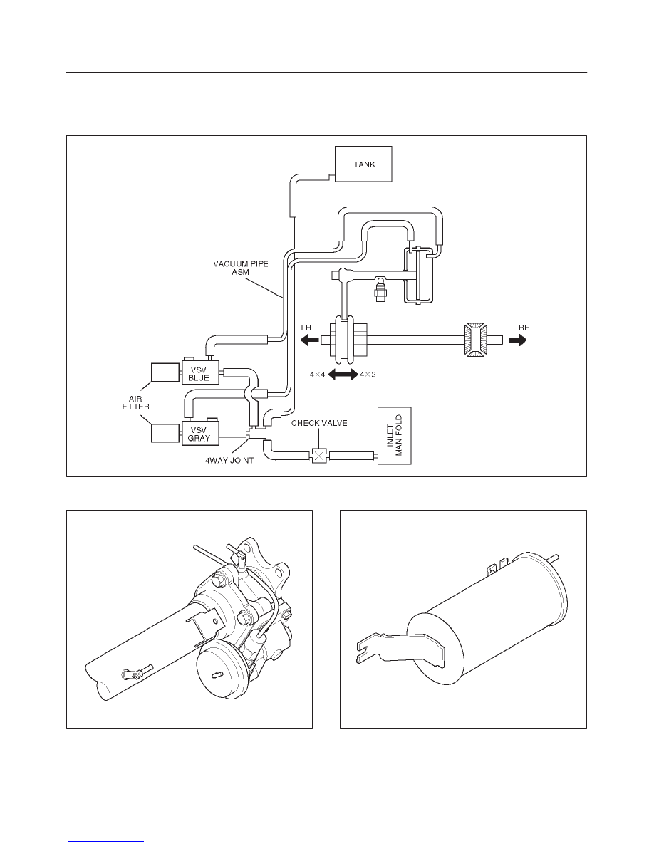
Shift On The Fly Vacuum Piping and Electrical Equipment
Vacuum Piping Diagram
C04RW005
Actuator Assembly
412RW024
Vacuum Tank
412RW025
4B–18 DRIVELINE CONTROL SYSTEM
Inspection and Repair
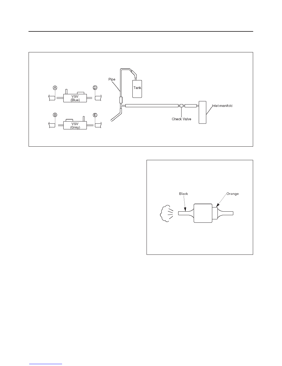
Vacuum Piping
C04RW004
1. Pull out the Hose A in figure and install a vacuum
gauge.
2. Plug up Hose B in figure to prevent the leak of
vacuum.
3. Start the engine and measure vacuum 2 or 3 minutes
afterward.
4. Repeat 1) and 2) but with Hose A plugged and Hose B
pulled out.
5. If vacuum measures –400mmHg, or if it shows a
sudden drop immediately after engine stop, inspect
the hose, tank, and pipe for damage.
NOTE: Be careful not to permit the entry of dust and
water during inspection.
6. Pull out Hose D in above illustration.
7. Plug Hose E in above illustration.
8. Make sure that Hose D in above illustration is under
atmospheric pressure.
9. Pull out Hose E and plug Hose D, and make sure that
Hose E is under atmospheric pressure.
10. If Check 8) or 9) has revealed stoppage, check and
see that there is no bend, foreign matter in the hose or
in the filter. If there is trouble, repair or replace.
Check Valve
C04RS004
1. Apply vacuum from the orange colored side(1).
Vacuum:–400mmHg
2. Check leakage of vacuum.
3. Make sure that vacuum cannot be applied from the
black colored side(2).
4. If vacuum is not applicable as much as –400mmHg,
and if there is resistance on the intake side, replace
with a new check valve.
Нет комментариевНе стесняйтесь поделиться с нами вашим ценным мнением.
Текст