Isuzu Rodeo UE. Manual — part 72
4B–19
DRIVELINE CONTROL SYSTEM
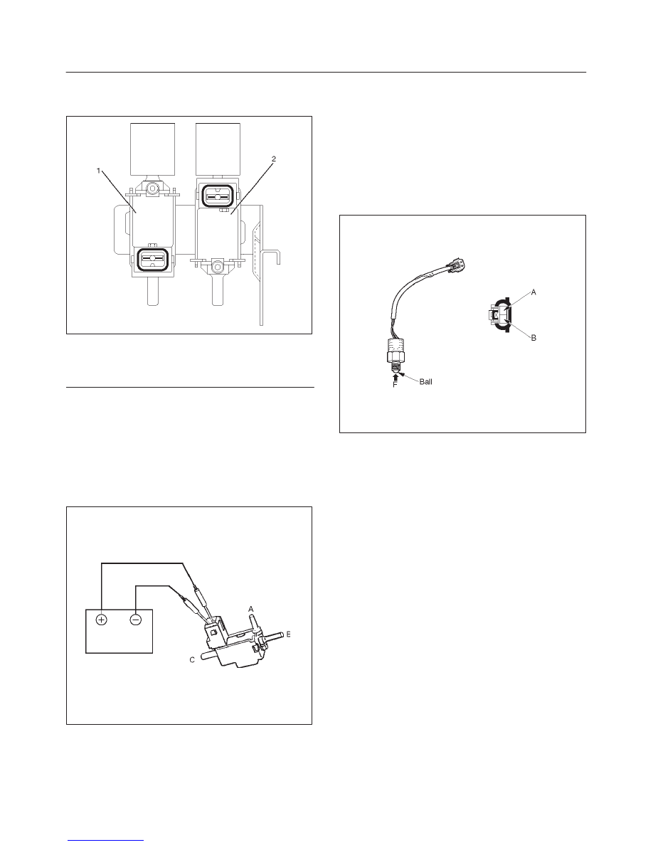
VSV Assembly
Inspect the vehicle side harness as follows:
412RW026
Legend
(1) Grey
(2) Blue
1. Remove connector.
2. Shift transfer lever to 2H and start the engine.
NOTE: The vehicle should not be started, with the engine
idling.
3. Make sure that there is continuity in the vehicle side of
harness. If there is no continuity, check transfer shift
switch and wiring.
Inspect the both VSVs as follows
F04RS004
1. With battery not connected (Usual).
A–C:There is continuity
B:Closed
2. With battery connected
A – B:There is continuity
C:Closed
3. If 1) and 2) fail, replace with a new VSV.
Functional Detective Switch
412RS048
1. With ball (1) being free
A–B:There is continuity
2. With ball forced into the switch
A–B:No continuity
3. If 1) and 2) fail, replace with a new switch.
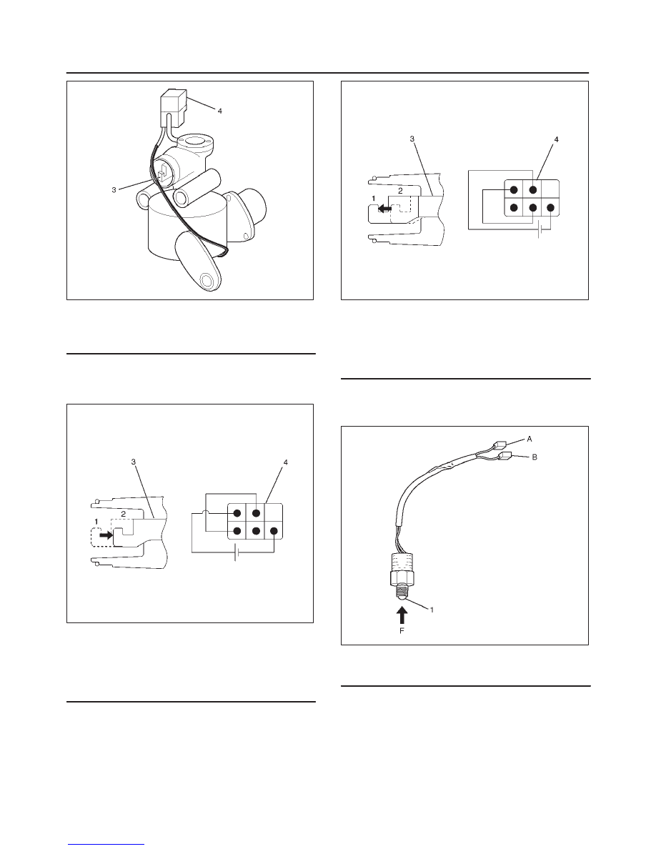
Motor Actuator Assembly
Inspect the function of the motor actuator assembly as
follows:
1. Disassemble the motor actuator from transfer rear
case.
4B–20 DRIVELINE CONTROL SYSTEM
412RW037
Legend
(3) Shift Rod
(4) Connector
2. Connect the terminals as shown in figure.
Shift rod of the motor actuator moves and stops
at 4WD position.
412RX001
Legend
(1) 2WD
(2) 4WD
(3) Shift Rod
(4) Connector
3. Connect the terminals as shown in figure.
Shift rod of the motor actuator moves and stops
at 2WD position.
412RX002
Legend
(1) 2WD
(2) 4WD
(3) Shift Rod
(4) Connector
4. If 2) and 3) fail, replace with a new motor actuator.
Transfer Position Switch
412RW040
Legend
(1) Ball
1. With ball being free.
A–B : There is continuity.
2. With ball forced into the switch.
A–B : No continuity.
3. If 1) and 2) fail, replace with a new switch.
4B–21
DRIVELINE CONTROL SYSTEM
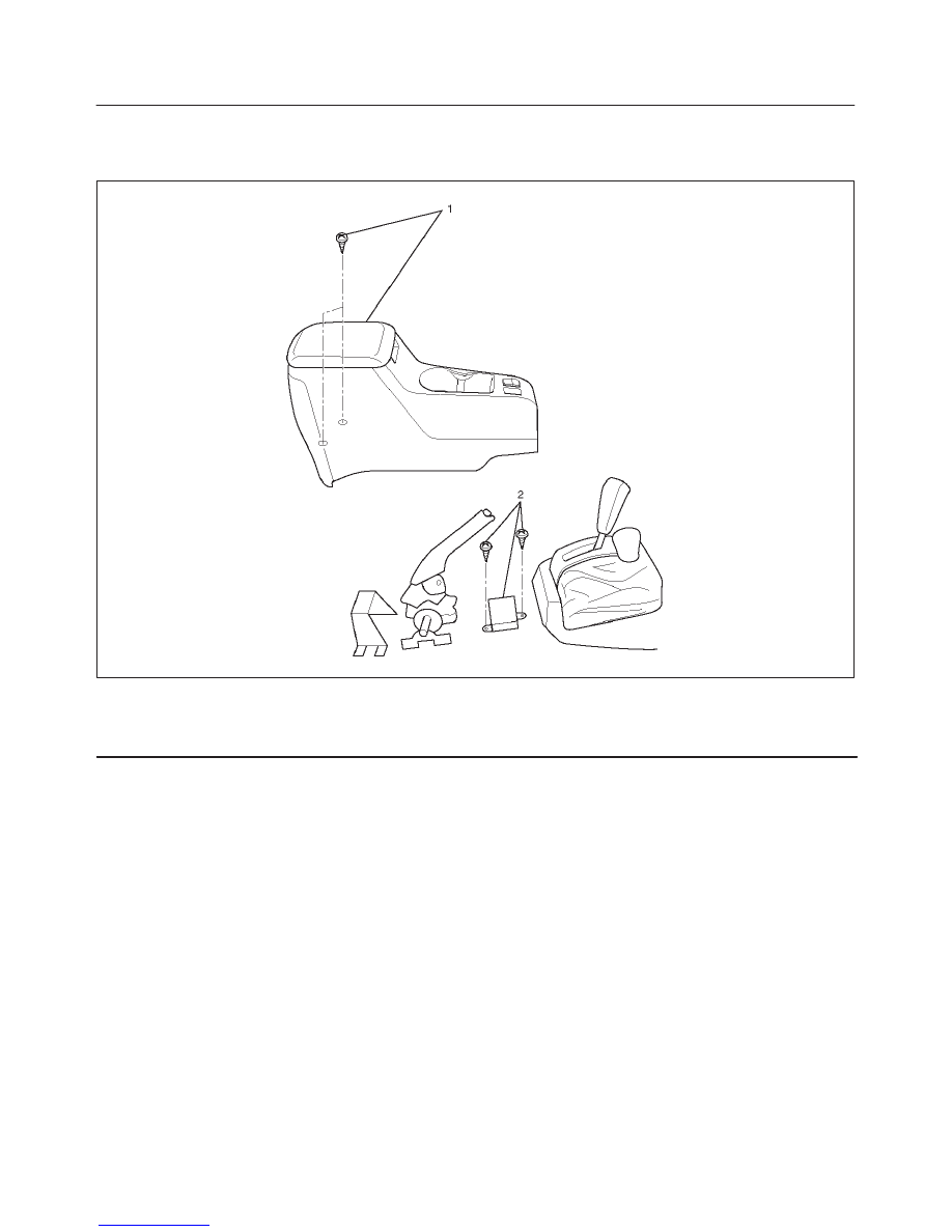
4WD Control Unit
4WD Control Unit Associated Parts
412RW042
Legend
(1) Center Console Assembly
(2) 4WD Control Unit
4B–22 DRIVELINE CONTROL SYSTEM
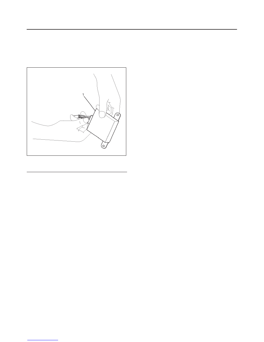
Removal
1. Remove center console assembly.
Refer to Interior Trim in Body and Accessories
section.
2. Remove two screws and harness connector (1) from
4WD control unit.
412RW041
Legend
(1) Harness Connector
Installation
1. Connect harness connector, then install 4WD control
unit.
2. Install center console assembly.
Нет комментариевНе стесняйтесь поделиться с нами вашим ценным мнением.
Текст