Isuzu Rodeo UE. Manual — part 63
DIFFERENTIAL (REAR)
4A2–17
425RW020
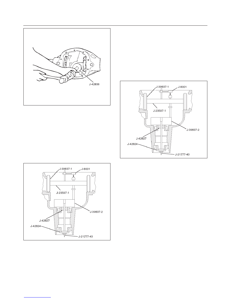
2. Clean all the gauge parts.
3. Lubricate the outer and inner bearings with axle
lubricant.
4. Place the bearings into the pinion bearing races.
5. Place the inner oil slinger onto the inner pinion
bearing.
NOTE: The inner oil slinger must be placed between
gauge plate and inner pinion bearing when measuring the
pinion depth.
6. Install gauge plate J–39837–2, inner J–42827 stud
and nut J–21777–43 and outer pilot J–42824 to the
pinion bore.
420RW005
7. Hold the stud stationary at the flats of the stud (and).
Tighten the stud nut
Torque: 2.2 N·m (1.6 lb ft)
8. Rotate the gauge plate and bearings several
complete revolutions to seat the bearings.
9. Tighten the stud nut until a torque of 1.6 to 2.2 N·m
(1.2 to 1.6 lb ft.) is required to keep the gauge plate in
rotation.
10. Assemble discs J–39837–1, arbor J–23597–1 and
dial indicator J–8001 to the side bearing bores.
NOTE: The bearing bores must be clean and burr-free.
420RW005
11. Install the side bearing caps and tighten the bolts to
the specified torque.
Torque: 108 N·m (80 lb ft)
12. Rotate the gauge plate until the gauging area is
parallel with the discs.
13. Position the arbor assembly in the carrier so that the
plunger is centered on the gauge area of the gauge
plate.
4A2–18
DIFFERNTIAL (REAR)
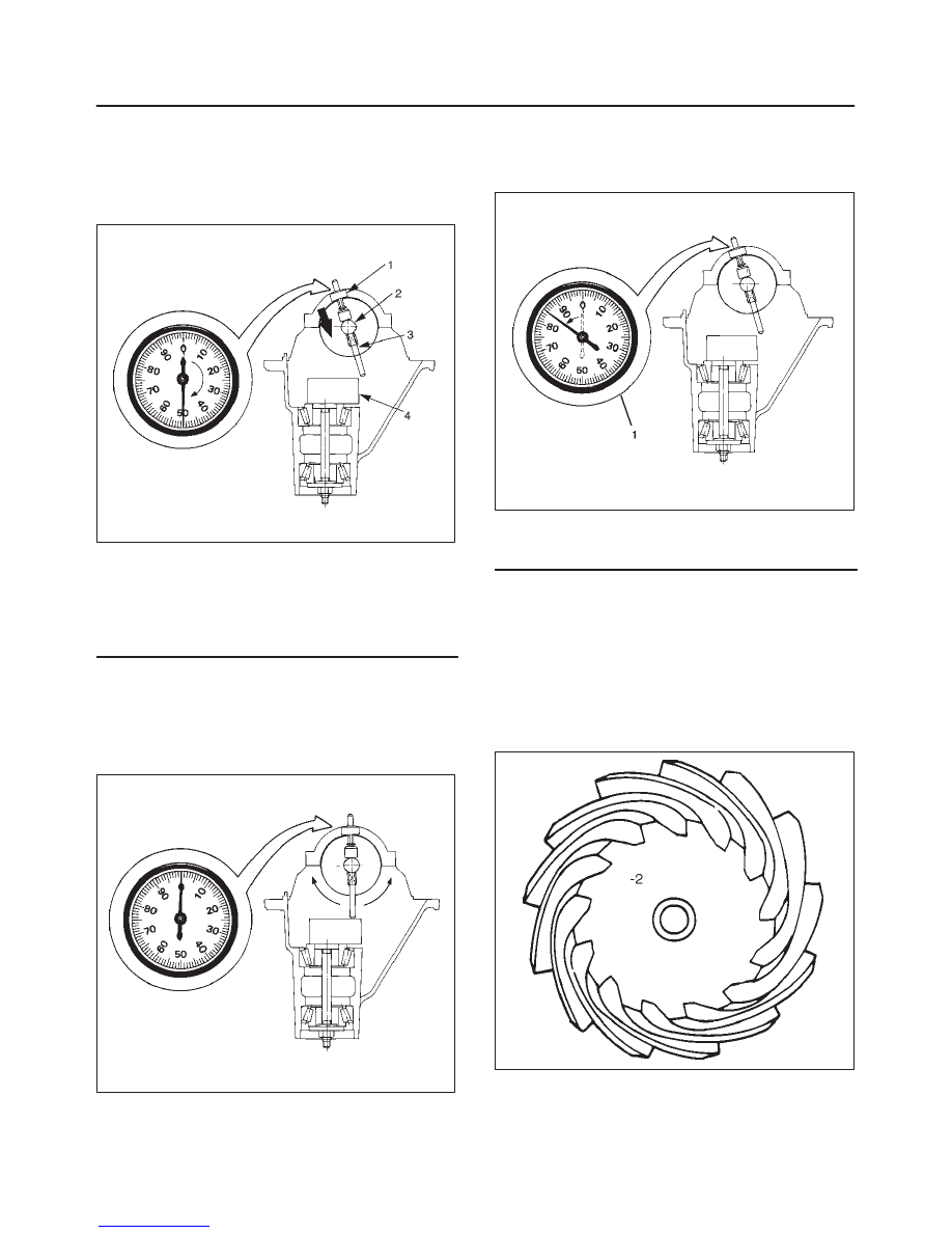
14. Set the dial indicator to “0”. Place it on the mounting
post of the gauging arbor with the contact button
touching the indicator pad.
Force the dial indicator downward until the needle has
made a half turn clockwise. Tighten down the dial
indicator in this position.
425RS020
Legend
(1) Dial Indicator
(2) Ganging Arbor
(3) Plunger
(4) Gaug Plate
15. Position the plunger on the gauge plate. Move the
gauging arbor slowly back and forth and locate the
position at which the dial indicator shows the greatest
defection. At this point, once again set the dial
indicator to “0”.
Repeat the procedure to verify the “0” setting.
425RS021
16. After the ZERO setting is obtained, rotate the gauging
arbor until the dial indicator rod does not touch the
gauging plate.
Record the number the dial indicator needle points to.
425RS022
Legend
(1) Example=Dial indicator reading of 0.085
17. Record the pinion depth code on the head of the drive
pinion.
The number indicates a necessary change in the
pinion mounting distance. A plus number indicates
the need for a greater mounting distance (which can
be achieved by decreasing the shim thickness). A
minus number indicates the need for a smaller
mounting distance (which can be achieved by
increasing the shim thickness). If examination
reveals pinion depth code “0”, the pinion is “nominal”.
425RS023
DIFFERENTIAL (REAR)
4A2–19
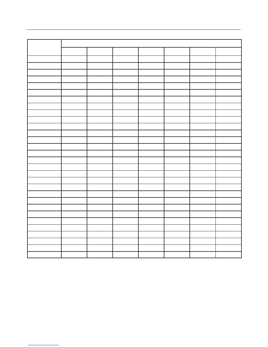
18. Select the shim using the chart;
Dial Indicator
Reading
Marking (inches)
Reading
(inches)
+3
+2
+1
0
–1
–2
–3
0.027
0.030
0.028
0.030
0.031
0.029
0.030
0.031
0.032
0.030
0.030
0.031
0.032
0.033
0.031
0.030
0.031
0.032
0.033
0.034
0.032
0.030
0.031
0.032
0.033
0.034
0.035
0.033
0.030
0.031
0.032
0.033
0.034
0.035
0.036
0.034
0.031
0.032
0.033
0.034
0.035
0.036
0.037
0.035
0.032
0.033
0.034
0.035
0.036
0.037
0.038
0.036
0.033
0.034
0.035
0.036
0.037
0.038
0.039
0.037
0.034
0.035
0.036
0.037
0.038
0.039
0.040
0.038
0.035
0.036
0.037
0.038
0.039
0.040
0.041
0.039
0.036
0.037
0.038
0.039
0.040
0.041
0.042
0.040
0.037
0.038
0.039
0.040
0.041
0.042
0.043
0.041
0.038
0.039
0.040
0.041
0.042
0.043
0.044
0.042
0.039
0.040
0.041
0.042
0.043
0.044
0.045
0.043
0.040
0.041
0.042
0.043
0.044
0.045
0.046
0.044
0.041
0.042
0.043
0.044
0.045
0.046
0.047
0.045
0.042
0.043
0.044
0.045
0.046
0.047
0.048
0.046
0.043
0.044
0.045
0.046
0.047
0.048
0.049
0.047
0.044
0.045
0.046
0.047
0.048
0.049
0.050
0.048
0.045
0.046
0.047
0.048
0.049
0.050
0.051
0.049
0.046
0.047
0.048
0.049
0.050
0.051
0.052
0.050
0.047
0.048
0.049
0.050
0.051
0.052
0.053
0.051
0.048
0.049
0.050
0.051
0.052
0.053
0.052
0.049
0.050
0.051
0.052
0.053
0.053
0.050
0.051
0.052
0.053
0.054
0.051
0.052
0.053
0.055
0.052
0.053
0.056
0.053
4A2–20
DIFFERNTIAL (REAR)
19. Remove bearing caps and depth gauging tools.
20. Install the correct pinion shim and inner oil slinger
onto pinion.
NOTE: Do not install pinion gear into housing at this time.
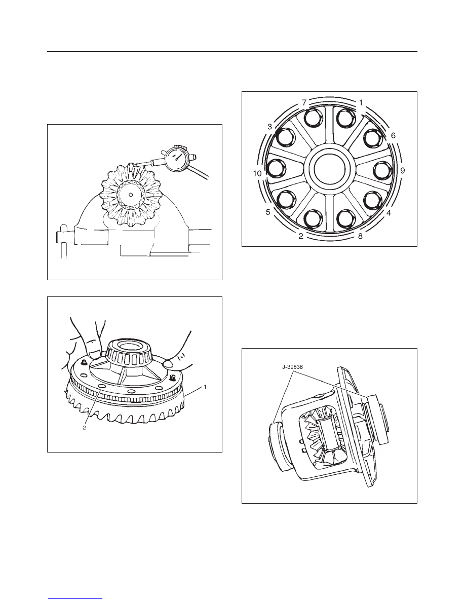
21. If the exciter ring was removed, install the new exciter
ring onto the differential case by pressing using the
ring gear as a pilot.
425RS047
22. Install ring gear(1) to the differential case(2)
425RW021
23. Install new ring gear bolts.
f
Tighten the ring gear bolts alternately in stages,
gradually pulling the ring gear onto the differential
case.
Tighten the ring gear bolts in sequence
Torque: 108 N·m (80 lb ft)
NOTE: Discard used bolts and install new ones.
415RS016
Side Bearing Preload Adjustment
1. The side bearing preload adjustment must be made
before installing the pinion.
2. The side bearing preload is adjusted by changing the
thickness of both hte left and right shims equally. This
maintain the original backlash.
3. Install master side bearings J–39836 onto the case.
Remove all nicks, burrs, dirt etc., from the hubs to
allow the master bearings to rotate freely.
425RW026
Нет комментариевНе стесняйтесь поделиться с нами вашим ценным мнением.
Текст