Isuzu Rodeo UE. Manual — part 336

6E2–99
RODEO 6VD1 3.2L ENGINE DRIVEABILITY AND EMISSIONS
Fuel System Diagnosis
(Cont'd)
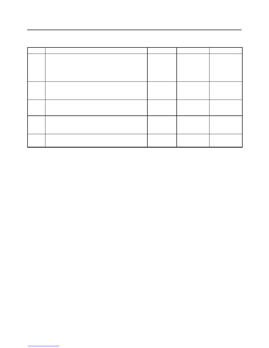
Step
No
Yes
Value(s)
Action
21
Is the fuel pressure indicated by the fuel pressure
gauge above the specified value?
0 kPa (0 psi)
Go to
Step 22
Go to
Step 23
22
1. Command the fuel pump “ON” with the Tech 2.
2. Using suitable pliers which will not damage the fuel
hose, gradually apply pressure with the pliers to
pinch the flexible fuel return hose closed.
CAUTION: Do not let the fuel pressure exceed
the second specified value.
Does the fuel pressure indicated by the fuel pressure
gauge rise above the first specified value?
376 kPa (55
psi). 414 kPa
(60 psi).
Go to
Step 11
Go to
Step 7
23
1. Command the fuel pump “ON” with the Tech 2.
2. Remove the fuel filler cap and listen for the sound of
the fuel pump running.
3. Turn the pump off.
Was the fuel pump running?
—
Go to
Step 7
Go to
Fuel
System
Electrical Test
Chart
6E2–100
RODEO 6VD1 3.2L ENGINE DRIVEABILITY AND EMISSIONS
Idle Air Control (IAC) System Check
Circuit Description
The powertrain control module (PCM) controls engine
idle speed with the idle air control (IAC) valve. To increase
idle speed, the PCM retracts the IAC valve pintle away
from its seat, allowing more air to bypass the throttle bore.
To decrease idle speed, it extends the IAC valve pintle
towards its seat, reducing bypass air flow. A Tech 2 will
read the PCM commands to the IAC valve in counts.
Higher counts indicate more air bypass (higher idle).
Lower counts indicate less air is allowed to bypass (lower
idle).
Diagnostic Aids
A slow, unstable, or fast idle may be caused by a non-IAC
system problem that cannot be overcome by the IAC
valve. Out of control range IAC Tech 2 counts will be
above 60 if idle is too low, and zero counts if idle is too
high. The following checks should be made to repair a
non-IAC system problem:
f
Vacuum leak (high idle) – If idle is too high, stop the
engine. Fully extend (low) IAC with the IAC motor
analyzer J 39027-A. Start the engine. If idle speed is
above 800 RPM, locate and correct the vacuum leak,
including the PCV system. Check for binding of the
throttle blade or linkage.
f
Lean heated oxygen sensor signal (high air/fuel ratio)
– The idle speed may be too high or too low. Engine
speed may vary up and down, and disconnecting the
IAC valve does not help. Diagnostic trouble codes
P0131, P0151, P0171, or P0174 may be set. Tech 2
oxygen (O2) voltage will be less than 100 mV (0.1 V).
Check for low regulated fuel pressure, water in fuel, or
a restricted injector.
f
Rich heated oxygen sensor signal (low air/fuel ratio) –
The idle speed will be too low. Tech 2 IAC counts will
usually be above 80. The system is obviously rich
and may exhibit black smoke in the exhaust.
Tech 2 O2 voltage will be fixed at about 750 mV (0.75
V). Check for high fuel pressure, or a leaking or
sticking injector. A silicon-contaminated heated
oxygen sensor will show an O2 voltage slow to
respond on the Tech 2.
f
Throttle body – Remove the IAC valve and inspect the
bore for foreign material.
f
IAC valve electrical connections – IAC valve
connections should be carefully checked for proper
contact.
f
PCV valve – An incorrect or faulty PCV valve may
result in an incorrect idle speed. Refer to
Diagnosis,
Rough Idle, Stalling. If intermittent poor driveability or
idle symptoms are resolved by disconnecting the
IAC, carefully recheck the connections and valve
terminal resistance, or replace the IAC.
Test Description
Number(s) below refer to the step number(s) on the
Diagnostic Chart.
1. The IAC motor analyzer J 39027-A is used to extend
and retract the IAC valve. Valve movement is
verified by an engine speed change. If no change in
engine speed occurs, the valve can be resettled
when removed from the throttle body.
2. This step checks the quality of the IAC movement in
step 1. Between 700 revolutions per minute (RPM)
and about 1500 RPM, the engine speed should
change smoothly with each flash of the tester light
in both extend and retract. If the IAC valve is
retracted beyond the control range (about 1500
RPM), it may take many flashes to extend the IAC
valve before engine speed will begin to drop. This
is normal on certain engines. Fully extending the
IAC may cause engine stall. This may be normal.
6. Steps 1 and 2 verified the proper IAC valve
operation. This step checks the IAC circuits. Each
lamp on the noid light should flash red and green
while the IAC valve is cycled. While the sequence
of color is not important, if either light is “OFF” or
does not flash red and green, check the circuits for
faults, beginning with poor terminal contacts.

6E2–101
RODEO 6VD1 3.2L ENGINE DRIVEABILITY AND EMISSIONS
Idle Air Control (IAC) System Check
Step
Action
Value(s)
Yes
No
1
1. Ignition “OFF.”
2. Connect the IAC motor analyzer J 37027-A to the
IAC valve.
3. Set the parking brake.
4. Block the wheels.
5. Turn the air conditioning “OFF.”
6. Idle the engine in Park (A/T) or Neutral (M/T).
7. Install the Tech 2. Display the RPM.
8. Use the IAC motor analyzer J 39027-A to extend
and retract the IAC valve.
9. The engine speed should decrease and increase as
the IAC is cycled.
Does the RPM change?
—
Go to
Step 2
Go to
Step 3
2
RPM should change smoothly with each flash of the
IAC motor analyzer J 39027-A light.
Does the RPM change within the range specified?
700-1500
RPM
Go to
Step 6
Go to
Step 3
3
Check the IAC passages.
Are the IAC passages OK?
—
Go to
Step 4
Go to
Step 5
4
Clear any obstruction from the IAC passages.
Is the action complete?
—
Verify repair
—
5
Replace the IAC. Refer to
On-Vehicle Service, Idle Air
Control Valve.
Is the action complete?
—
Verify repair
—
6
1. Install the appropriate IAC noid light from J
39027-A into the powertrain control module
harness.
2. Cycle the IAC motor analyzer J 39027-A and
observe the noid lights.
3. Both the lights should cycle red and green, but
never “OFF,” as the RPM is changed over its range.
Do the noid lights cycle red and green?
—
Go to
Step 7
Go to
Step 8
7
1. Use the other connector on the IAC motor analyzer
J 39027-A pigtail.
2. Check the resistance across the IAC coils.
Measure the resistance between terminal A and
terminal B.
3. Measure the resistance between terminal C and
terminal D.
Is the resistance within the specified range?
40-80 ohms
Go to
Step 9
Go to
Step 10
8
If the circuits did not test green and red, check the
following:
f
Faulty connector terminal contacts
f
Open circuits, including connections
f
Circuits shorted to ground or voltage
f
Faulty powertrain control module connection or
powertrain control module.
Are repairs necessary?
—
Go to
Step 13
—
6E2–102
RODEO 6VD1 3.2L ENGINE DRIVEABILITY AND EMISSIONS
Idle Air Control (IAC) System Check
(Cont'd)
Step
No
Yes
Value(s)
Action
9
1. Check the resistance between the IAC terminal B
and terminal C.
2. Check the resistance between the IAC terminal A
and terminal D.
Is the resistance infinite?
—
Go to
Step 11
Go to
Step 12
10
Replace the IAC. Refer to
On-Vehicle Service, Idle Air
Control Valve.
Is the action complete?
—
Go to
Step 7
—
11
Check the IAC valve and circuit.
Are the IAC valve and circuit OK?
—
Refer to
Diagnostic
Aids
Go to
Step 12
12
Replace the IAC. Refer to
On-Vehicle Service, Idle Air
Control Valve.
Is the action Complete?
—
Go to
Step 9
—
13
Repair as necessary.
Is the action complete?
—
Go to
Step 6
—
Нет комментариевНе стесняйтесь поделиться с нами вашим ценным мнением.
Текст