Isuzu Rodeo UE. Manual — part 390

6E2–315
RODEO 6VD1 3.2L ENGINE DRIVEABILITY AND EMISSIONS
DTC P0406 – EGR High Voltage
Step
Action
Value(s)
Yes
No
1
Was the “On-Board Diagnostic (OBD) System Check”
performed?
—
Go to
Step 2
Go to
OBD
System
Check
2
1. Ignition “ON,” engine “OFF”, review and record
Tech 2 Failure Records Data.
2. Operate the vehicle within Failure Records
conditions as noted.
3. Using a Tech 2, monitor “DTC” info for DTC P0406
until the DTC P0406 test runs. Note the result.
Does the Tech 2 indicates DTC P0406 failed this
ignition?
—
Go to
Step 3
Refer to
Diagnostic
Aids
3
1. Disconnect the EGR valve harness connector.
2. Inspect the EGR valve and connectors for damaged
pin or terminals.
Were there any damaged pins or terminals?
—
Go to
Step 4
Go to
Step 5
4
Repair the damaged pin or terminal.
Is the action complete?
—
Verify repair
Is the action
complete?
5
1. Disconnect the EGR harness connector.
2. Ignition “ON”.
3. At the EGR valve, use a DVM to check the voltage
at the 5 volt reference wire (RED).
Did the DVM indicate the specified value?
4–6 V
Go to
Step 8
Go to
Step 6
6
1. Ignition “ON”.
2. At the PCM connector, backprove with a DVM at the
5 volt reference for the EGR valve.
Did the DVM indicare the specified value?
4–6 V
Go to
Step 7
Go to
Step 16
7
Repair the open 5 volt reference circuit
Is the action complete?
—
Verify repair
—
8
1. Ignition “OFF”
2. Disconnect the EGR harness.
3. Use a DVM to check for an resistance between D (5
V reference) and B (Sensor Ground) at EGR sensor
terminals.
NOTE: J-35616 Connector Test Adapter Kit may be
useful for gaining access to the recessed pins on the
valve.
Was the measured resistance in range?
5 to 5 K
W
Go to
Step 9
Go to
Step 15
9
1. Ignition “OFF”.
2. Disconnect the EGR harness.
3. Use a DVM to check for an resistance between B
and C at EGR sensor terminal.
Is there an open circuit?
—
Go to
Step 15
Go to
Step 10
10
1. Ignition “OFF”.
2. Disconnect the EGR harness at PCM connector.
3. Use a DVM to check for shorted wire between A1
and B7.
Is there a shorted wire?
—
Go to
Step 14
Go to
Step 11

6E2–316
RODEO 6VD1 3.2L ENGINE DRIVEABILITY AND EMISSIONS
DTC P0406 – EGR High Voltage
(Cont'd)
Step
No
Yes
Value(s)
Action
11
1. Ignition “ON”.
2. Use a DVM to backprove at terminal C of EGR
valve for voltage.
Was measured voltage more than 4.8 V?
more than 4.8
V
Go to
Step 12
Go to
Step 12
12
1. Ignition “ON”.
2. Stay the EGR harness connected.
3. Check voltage by backproving at PCM B7 terminal.
Was voltage more than 4.8 V?
4.8 V
Go to
Step 16
Go to
Step 13
13
1. Locate short circuit at EGR harness between RED
to RED or GREEN, RED to YEL.
2. Replace EGR harness.
Is the action complete?
—
Verify repair
—
14
Replace EGR harness.
Is the action complete?
—
Verify repair
—
15
Replace the EGR valve.
Does DTC P1404 still fail “DTC test on the Tech 2?
—
Go to
Step 16
Verify repair
16
Replace the PCM.
IMPORTANT: The replacement PCM must be
programmed. Refer to
On-Vehicle Service in
Powertrain Control Module and Sensors for
procedures.
And also refer to latest Service Bulletin.
Check to see if the Latest software is released or not.
And then Down Load the LATEST PROGRAMMED
SOFTWARE to the replacement PCM.
Is the action complete?
—
Verify repair
—
6E2–317
RODEO 6VD1 3.2L ENGINE DRIVEABILITY AND EMISSIONS
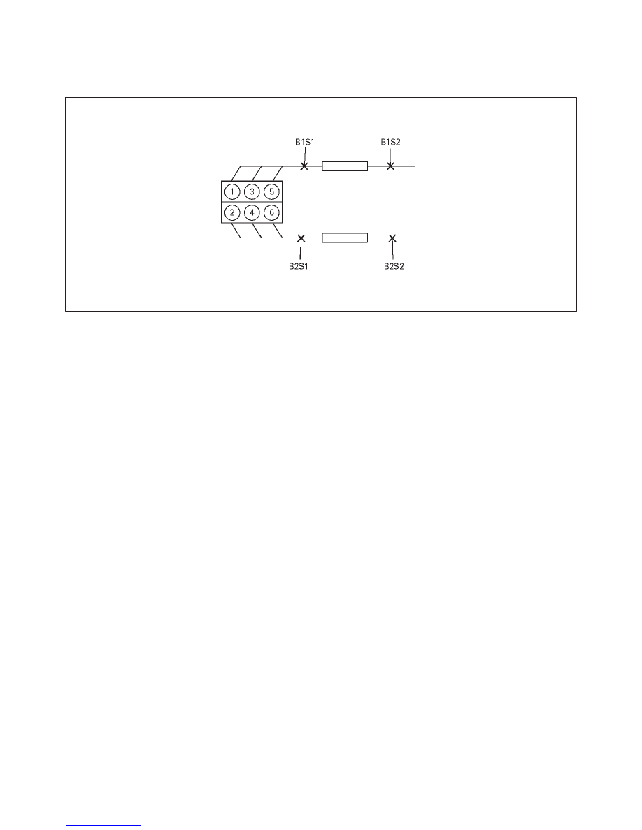
Diagnostic Trouble Code (DTC) P0420 TWC System Low Efficiency Bank 1
T321075
Circuit Description
To control emissions of hydrocarbons (HC), carbon
monoxide (CO), and oxides of nitrogen (NOx), a
three-way catalyst (TWC) is used. The catalyst promotes
a chemical reaction which oxidizes the HC and CO
present in the exhaust gas, converting them into
harmless water vapor and carbon dioxide. The catalyst
also reduces NOx, converting it to nitrogen. The
powertrain control module (PCM) has the ability to
monitor this process using the Bank 1 HO2S 1 and the
Bank 1 HO2S 2 heated oxygen sensors. The Bank 1
HO2S 1 sensor produces an output signal which indicates
the amount of oxygen present in the exhaust gas entering
the three-way catalytic converter. The Bank 1 HO2S 2
sensor produces an output signal which indicates the
oxygen storage capacity of the catalyst; this in turn
indicates the catalyst’s ability to convert exhaust gases
efficiently. If the catalyst is operating efficiently, the Bank
1 HO2S 1 signal will be far more active than that produced
by the Bank 1 HO2S 2 sensor. If the PCM detects a level
of Bank 1 HO2S 2 activity that indicates the catalyst is no
longer operating efficiently, DTC P0420 will be set.
Conditions for Setting the DTC
f
No related DTCs.
f
The engine is operating in “closed loop.”
f
Engine air load is below 99%.
f
Engine coolant temperature is above 60
°
C (140
°
F).
f
Mass air flow is between 8 g/second and 50 g/second.
f
Change in engine load is below 8%.
f
Engine speed is below 3500 RPM.
f
Vehicle speed is between 26 km/h and 123 km/h (16
mph and 75 mph).
f
Catalyst temperature is above 399
°
C (750
°
F).
f
The PCM determines that the catalyst’s oxygen
storage capacity is below the acceptable threshold.
Action Taken When the DTC Sets
f
The PCM will illuminate the malfunction indicator lamp
(MIL) the first time the fault is detected.
f
The PCM will store conditions which were present
when the DTC was set as Freeze Frame and in the
Failure Records data.
Conditions for Clearing the MIL/DTC
f
The PCM will turn the MIL “OFF” on the third
consecutive trip cycle during which the diagnostic has
been run and the fault condition is no longer present.
f
A history DTC P0420 will clear after 40 consecutive
warm-up cycles have occurred without a fault.
f
DTC P0420 can be cleared by using the Tech 2 “Clear
Info” function or by disconnecting the PCM battery
feed.
Diagnostic Aids
Check for the following conditions:
f
Poor connection at PCM – Inspect harness connectors
for backed-out terminals, improper mating, broken
locks, improperly formed or damaged terminals, and
poor terminal-to-wire connection.
f
Damaged harness – Inspect the wiring harness for
damage. If the harness appears to be OK, observe the
display on the Tech 2 while moving connectors and
wiring harnesses related to the sensor. A change in the
display will indicate the location of the fault.
Reviewing the Failure Records vehicle mileage since the
diagnostic test last failed may help determine how often
the condition that caused the DTC to be set occurs. This
may assist in diagnosing the condition.
f
Bank 1 HO2S 1/Bank 1 HO2S 2 Activity Test:
– Ensure that the engine is fully warmed up.
– Using a Tech 2, monitor Bank 1 HO2S 1 and Bank 1
HO2S 2 displays in “Park” while using the Tech 2 IAC
RPM control function to maintain a mass air flow of
10 g/second. Compare the amount of activity
(frequency and amplitude) on Bank 1 HO2S 1 to the
activity on Bank 1 HO2S 2 over a 30 second period.
If the amount of activity on Bank 1 HO2S 2 is nearly as
great as the activity on Bank 1 HO2S 1, a problem exists.
Use the DTC P0420 diagnostic chart. If much less activity
is noted on Bank 1 HO2S 2, the system is functioning
properly.
6E2–318
RODEO 6VD1 3.2L ENGINE DRIVEABILITY AND EMISSIONS
The “TWC Monitor Test Counter” displayed on the Tech 2
may be used to monitor the progress of the TWC
diagnostic. To complete the TWC diagnostic with a good
catalyst, the counter must be allowed to increment to 49
samples and roll over to 0 at least twice. A failed catalyst
will require three or more 50-sample tests to report a
failure.
Test Description
Number(s) below refer to the step number(s) on the
Diagnostic Chart.
7. Difficulty completing the DTC P0420 “Status This
Ign.” test may be encountered in areas where test
conditions cannot be maintained easily, especially in
urban areas. To minimize the amount of driving
required to complete the DTC P0420 “Status This
Ign.” test, use the following procedure:
f
Allow the engine to warm completely.
f
With the vehicle in “Park,” monitor mass air flow on
the Tech 2 and hold part throttle to maintain a
reading of over 12 g/second for at least 2 minutes.
This will achieve the “warm catalyst” required for
running the test.
f
Operate the vehicle in second or third gear to remain
in the DTC P0420 test conditions described in
“Conditions for Setting the DTC” as much as
possible. If you must stop the vehicle, maintain the
“warm catalyst” criteria as follows:
– Place the vehicle in “Park” or “Neutral.”
– Hold part throttle to maintain a mass air flow
reading of over 15 g/second for the duration of the
stop.
Нет комментариевНе стесняйтесь поделиться с нами вашим ценным мнением.
Текст