Isuzu Rodeo UE. Manual — part 389

6E2–311
RODEO 6VD1 3.2L ENGINE DRIVEABILITY AND EMISSIONS
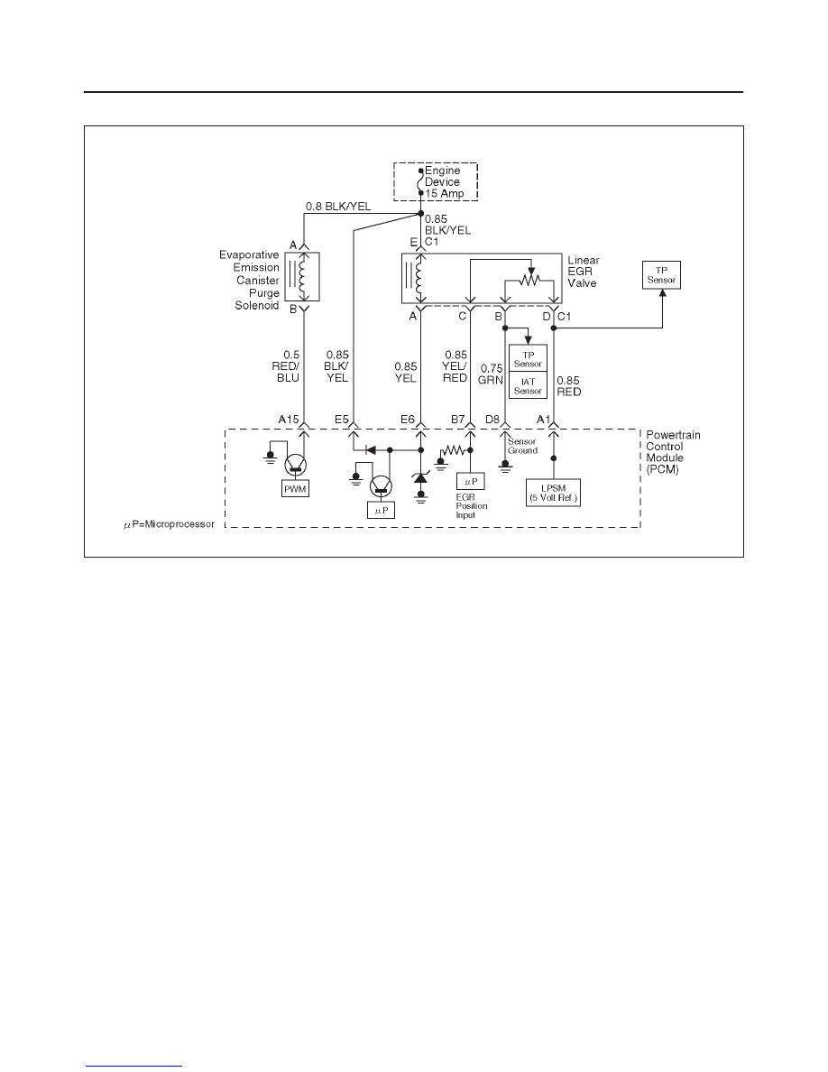
Diagnostic Trouble Code (DTC) P0405 EGR Low Voltage
D06RW055
Circuit Description
The powertrain control module (PCM) monitors the EGR
valve pintle position input to ensure that the valve
responds properly to command from the PCM. If current
pintle position voltage indicates less than 0.1 V and last
more than 10 seconds, then the PCM will set DTC P0405.
Conditions for Setting the DTC
f
Ignition voltage is between 11 and 16 volts.
f
EGR pintle position output voltage is less than 0.1 volt
and last more than 10 sec. Action taken when the DTC
sets.
Action Taken When the DTC Sets
f
The PCM will illuminate the malfunction indicator lamp
(MIL) as soon as failure detected.
f
The PCM will store conditions which were present
when the DTC was set as Freeze Frame and in Failure
Records data.
Conditions for Clearing the MIL/DTC
f
The PCM will turn the MIL “OFF” on the third
consecutive trip cycle during which the diagnostic has
been run and the fault condition is no longer present.
f
A history DTC P0402 will clear after 40 consecutive
warm-up cycles have occurred without a fault.
f
DTC P0405 can be cleared by using the Tech 2 “Clear
Info” function or by disconnecting the PCM battery
feed.
Diagnostic Aids
Check for the following conditions:
f
Poor connection or damaged harness – Inspect the
wiring harness for damage. If the harness appears to
be OK, observe the EGR actual position display on the
Tech 2 while moving connectors and wiring harnesses
related to EGR valve. A change in the display will
indicate the location of the fault.

6E2–312
RODEO 6VD1 3.2L ENGINE DRIVEABILITY AND EMISSIONS
DTC P0405 – EGR Low Voltage
Step
Action
Value(s)
Yes
No
1
Was the “On-Board Diagnostic (OBD) System Check”
performed?
—
Go to
Step 2
Go to
OBD
System
Check
2
1. Ignition “ON,” engine “OFF”, review and record
Tech 2 Failure Records Data.
2. Operate the vehicle within Failure Records
conditions as noted.
3. Using a Tech 2, monitor “DTC” info for DTC P0405
until the DTC P0405 test runs. Note the result.
Does the Tech 2 indicates DTC P0405 failed this
ignition?
—
Go to
Step 3
Refer to
Diagnostic
Aids
3
1. Disconnect the EGR valve harness connector.
2. Inspect the EGR valve and connectors for damaged
pin or terminals.
Were there any damaged pins or terminals?
—
Go to
Step 4
Go to
Step 5
4
Repair the damaged pin or terminal.
Is the action complete?
—
Verify repair
—
5
1. Disconnect the EGR harness connector.
2. Ignition “ON”.
3. At the EGR valve, use a DVM to check the voltage
at the 5 volt reference wire (RED) and ground (B).
Did the DVM indicate the specified value?
4–6 V
Go to
Step 6
Go to
Step 7
6
1. Disconnect the EGR harness connector.
2. Measure resistance between terminal B and D.
Was resistance in range?
5–5.5 K
W
Go to
Step 10
Go to
Step 17
7
1. Ignition “ON”.
2. At the PCM connector, backprove with a DVM at the
5 volt reference for the EGR valve.
Did the DVM indicate the specified value?
4–6 V
Go to
Step 8
Go to
Step 18
8
Repair the open 5 volt reference circuit.
Is the action complete?
—
Verify repair
—
9
Repair the damaged sensor ground wire.
Is the action complete?
—
Verify repair
—
10
1. Disconnect the EGR harness
2. Use an ohmmeter to measure between the pintle
position pin and the sensor ground pin on the EGR
valve.
NOTE: J-35616 Connector Test Adapter Kit may be
useful for gaining access to the recessed pins on the
valve.
Was the ohmmeter reading approximately equal to the
specified value?
1 to 1.25 K
W
Go to
Step 13
Go to
Step 17
11
1. Ignition “ON”.
2. Backprobe with a DVM to measure voltage at EGR
valve pintle position pin and sensor ground pin.
Was voltage in range?
Less than 0.1
V
Go to
Step 17
Go to
Step 12

6E2–313
RODEO 6VD1 3.2L ENGINE DRIVEABILITY AND EMISSIONS
DTC P0405 – EGR Low Voltage
(Cont'd)
Step
No
Yes
Value(s)
Action
12
1. Ignition “ON”.
2. Backprobe with a DVM to measure voltage at PCM
sensor ground pin and pintle position pin.
Was voltage in range?
Less than 0.1
V
Go to
Step 13
Go to
Step 18
13
1. Ignition “OFF”.
2. Disconnect the EGR harness.
3. Check short circuit between EGR pintle position
circuit and EGR ground circuit.
Was any short circuit?
—
Go to
Step 14
Go to
Step 18
14
Locate and repair the short to ground in the pintle
position circuit
Is the action complete?
—
Verify repair
—
15
1. Ignition “OFF”.
2. Disconnect the PCM.
3. Ignition “ON”.
4. Measure the voltage between the EGR pintle
position circuit and ground.
Is the measured voltage near the specified value?
Less than 0.1
V
Go to
Step 17
Go to
Step 16
16
Check for a short circuit between other wires and the
pintle position circuit
Is there any short circuit?
—
Repair short
circuit
Verify repair
Go to
Step 17
17
Replace the EGR valve.
Does DTC P1404 still fail “DTC test on the Tech 2?
—
Go to
Step 18
Verify repair
18
Examine the PCM pin and terminal connection.
Was there a damaged terminal?
—
Go to
Step 4
Go to
Step 19
19
Replace the PCM.
IMPORTANT: The replacement PCM must be
programmed. Refer to
On-Vehicle Service in
Powertrain Control Module and Sensors for
procedures.
And also refer to latest Service Bulletin.
Check to see if the Latest software is released or not.
And then Down Load the LATEST PROGRAMMED
SOFTWARE to the replacement PCM.
Is the action complete?
—
Verify repair
—
6E2–314
RODEO 6VD1 3.2L ENGINE DRIVEABILITY AND EMISSIONS
Diagnostic Trouble Code (DTC) P0406 EGR High Voltage
D06RW055
Circuit Description
The powertrain control module (PCM) monitors the EGR
valve pintle position input to ensure that the valve
responds properly to command from the PCM. If current
pintle position voltage indicates more than 4.8 V and last
more than 10 seconds, then the PCM will set DTC P0406.
Conditions for Setting the DTC
f
Ignition voltage is between 11 and 16 volts.
f
EGR pintle position output voltage is more than 4.8 volt
and last more than 10 sec.
Action Taken When the DTC Sets
f
The PCM will illuminate the malfunction indicator lamp
(MIL) as soon as failure detected.
f
The PCM will store conditions which were present
when the DTC was set as Freeze Frame and in Failure
Records data.
Conditions for Clearing the MIL/DTC
f
The PCM will turn the MIL “OFF” on the third
consecutive trip cycle during which the diagnostic has
been run and the fault condition is no longer present.
f
A history DTC P0402 will clear after 40 consecutive
warm-up cycles have occurred without a fault.
f
DTC P0404 can be cleared by using the Tech 2 “Clear
Info” function or by disconnecting the PCM battery
feed.
Diagnostic Aids
Check for the following conditions:
f
Poor connection or damaged harness – Inspect the
wiring harness for damage. If the harness appears to
be OK, observe the EGR actual position display on the
Tech 2 while moving connectors and wiring harnesses
related to EGR valve. A change in the display will
indicate the location of the fault.
Нет комментариевНе стесняйтесь поделиться с нами вашим ценным мнением.
Текст