Isuzu Rodeo UE. Manual — part 542
8D–16
WIRING SYSTEM
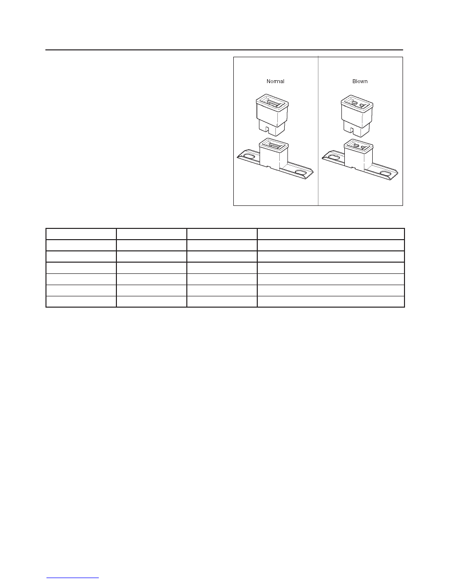
Fusible Link
The fusible link is primarily used to protect circuits where
high amounts of current flow and where it would not be
practical to use a fuse. For example, the starter circuit.
When a current overload occurs, the fusible link melts
open and interrupts the flow of current so as to prevent the
rest of the wiring harness from burning.
Determine the cause of the overload before replacing the
fusible link. the replacement fusible link must have the
same amperage specification as the original fusible link.
Never replace a blown fusible link with fusible link of a
different amperage specification. Doing so can result in
an electrical fire or other serious circuit damage.
A blown fusible link is easily identified as shown in the
figure.
D08RW054
Fusible Link Specifications
Type
Rating
Case Color
Maximum Circuit Current (A)
Connector
30A
Pink
15
Connector
40A
Green
20
Bolted
50A
Red
25
Bolted/Connector
60A
Yellow
30
Bolted
80A
Black
40
Bolted
100A
Blue
50
8D–17
WIRING SYSTEM
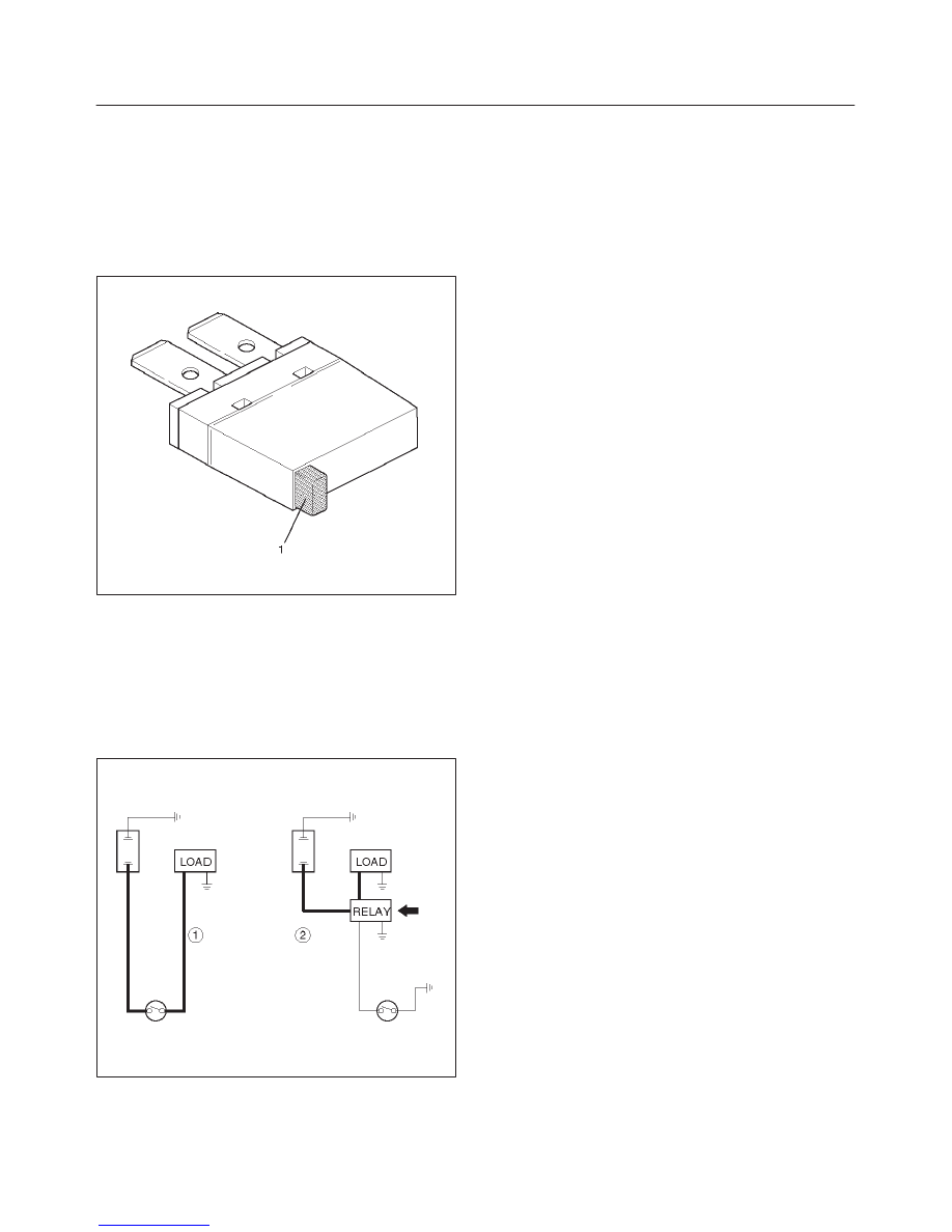
Circuit Breaker
The circuit breaker is a protective device designed to
open the circuit when a current load is in excess of rated
breaker capacity. If there is a short or other type of
overload condition in the circuit, the excessive current will
open the circuit between the circuit breaker terminals.
The reset knob (1) pops out when the circuit is open. Push
the reset knob in place to restore the circuit after repairing
it.
D08RW155
Relay
Battery and load location may require that a switch be
placed some distance from either component. This
means a longer wire and a higher voltage drop (1).
The installation of a relay between the battery and the
load reduces the voltage drop (2).
Because the switch controls the relay, amperage through
the switch can be reduced.
D08RW156
8D–18
WIRING SYSTEM
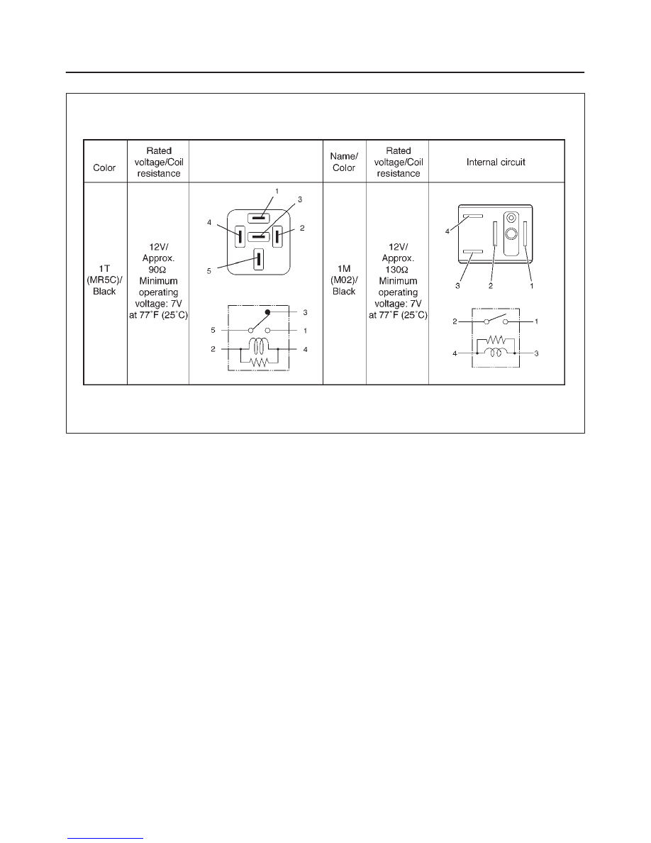
Relay Specifications and Configurations
F00RX012
*
Relay contact shown in the wiring diagram indicates
condition before actuation.
8D–19
WIRING SYSTEM
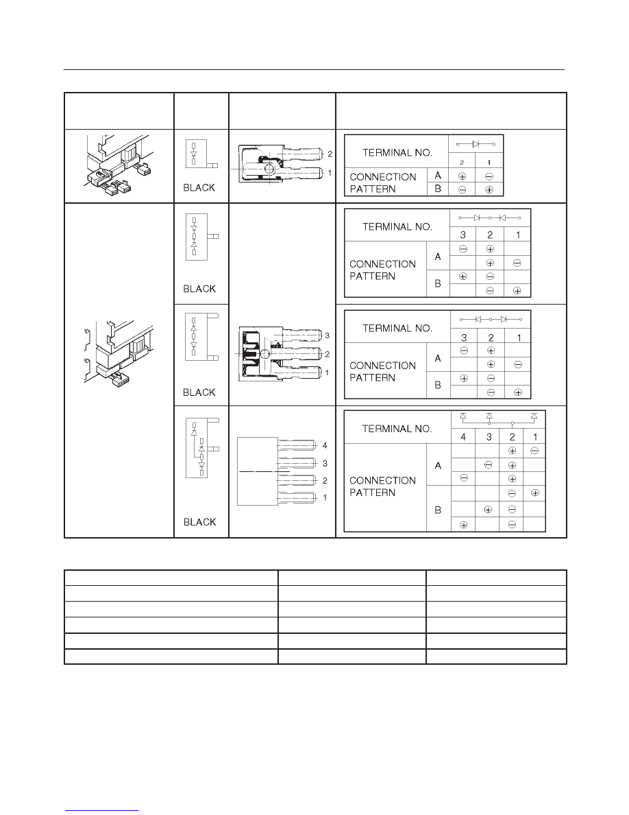
Diode – Diode Specifications and Configurations
SHAPE
MARK /
COLOR
CONSTRUCTION
CHECKING: THERE SHOULD BE CONTINUITY
IN EITHER A OR B WHEN A CIRCUIT TESTER
IS CONNECTED WITH DIODE TERMINAL
Diode – Maximum Rating (Temp. = 77
°
F (25
°
C)
Items
Rating
Remarks
Peak reverse voltage
400V
Transient peak reverse voltage
500V
Average output current
1.5A
Temp. = 104
°
F (40
°
C)
Working ambient temperature
–22
°
F
∼
176
°
F (–30
°
C
∼
80
°
C)
Storage temperature
–40
°
F
∼
212
°
F (–40
°
C
∼
100
°
C)
Нет комментариевНе стесняйтесь поделиться с нами вашим ценным мнением.
Текст