Isuzu Rodeo UE. Manual — part 613
8F–25
BODY STRUCTURE
General Description (Body)
This publication contains essential removal, installation,
adjustment and maintenance procedures.
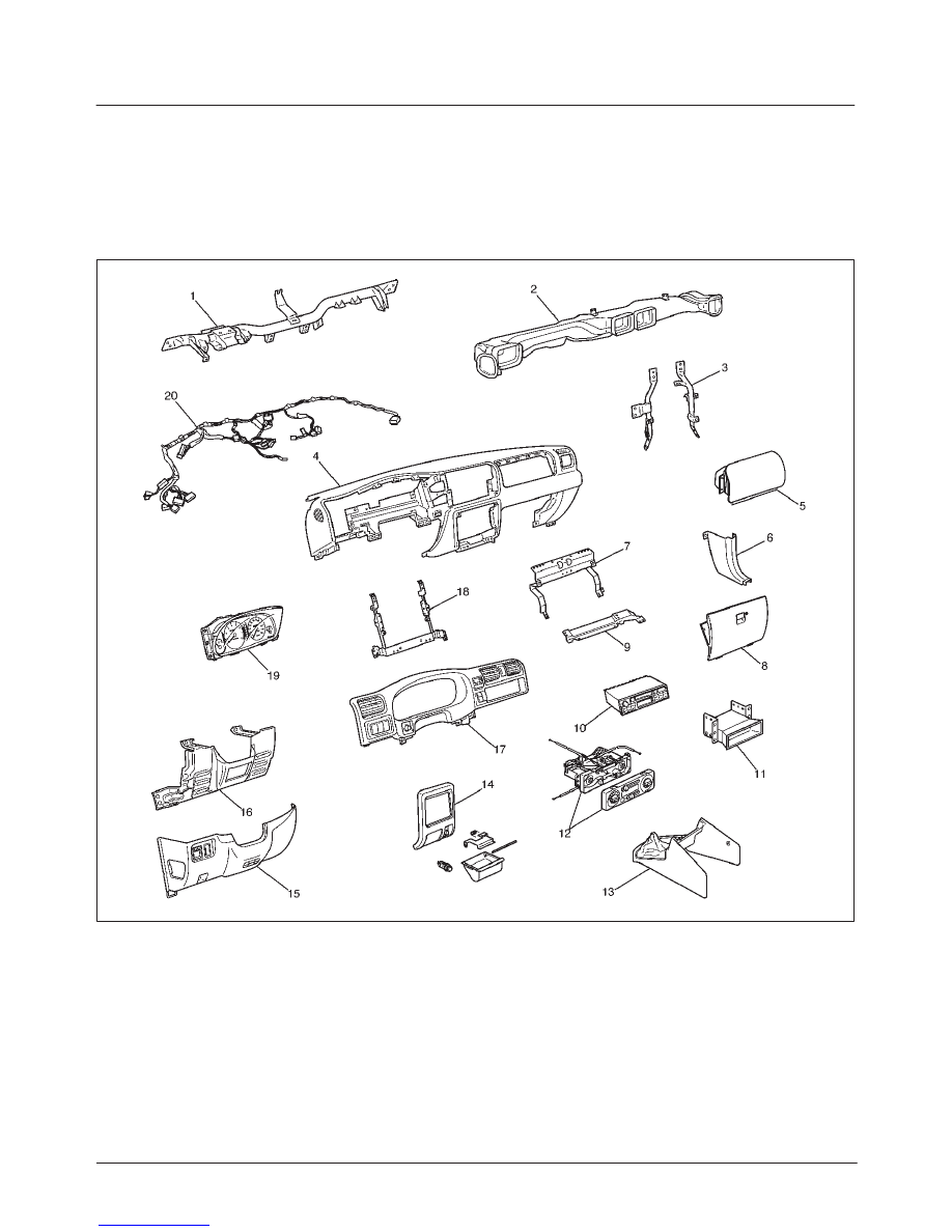
Instrument Panel Assembly
Parts Location
740RX043
Legend
(1) Cross Beam
(2) Vent Duct Assembly
(3) Instrument Panel Bracket
(4) Instrument Panel Assembly
(5) Passenger Inflator Module
(6) Dash Side Trim Panel
(7) Passenger Knee Bolster Reinforcement
Assembly
(8) Glove Box
(9) Passenger Lower Bracket
(10) Radio Assembly
(11) Audio Sub Box
(12) Control Lever Assembly
(13) Front Console Assembly
(14) Lower Center Cover
(15) Instrument Panel Driver Lower Cover
Assembly
(16) Driver Knee Bolster Assembly
(17) Meter Cluster Assembly
(18) Instrument Panel Center Reinforcement
(19) Meter Assembly
(20) Instrument Harness Assembly

8F–26
BODY STRUCTURE
Removal
CAUTION: For precautions on installation or
removal of SRS – air bag system, refer to
Supplemental Restraint System (SRS) – AIR BAG in
Restraint section.
1. Disconnect the battery ground cable.
2. Remove lower center cover.
f
Remove screw (1) and pull out the cover at the clip
positions.
f
Disconnect the cigarette lighter connector (2).
470RW001
3. Remove front and rear console.
4. Remove dash side trim panels
f
Remove sill plates, then remove panels.
5. Remove glove box.
f
Remove the 2 fixing screws.
470RW002
6. Remove instrument panel driver lower cover
assembly.
f
Remove the engine hood opener 2 fixing screws
and 6 fixing screws.
610RS005
7. Remove meter cluster assembly.
f
Remove 5 fixing screws, 2 clips and 8 switch
connectors.
8. Remove driver knee bolster assembly.
f
Remove the 6 fixing bolts and screw.
9. Remove control lever assembly.
f
Remove 4 bolts and disconnect 3 control cables on
the unit side and 3 harness connectors.
10. Remove radio and audio sub box assembly.
f
Remove 4 screws.
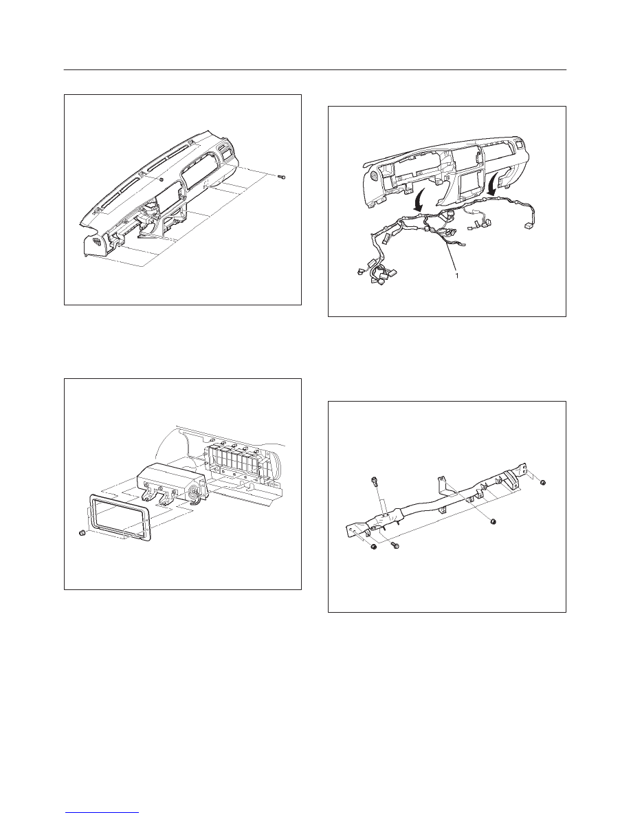
11. Remove Instrument panel assembly.
CAUTION: For precautions on installation or
removal of SRS – air bag system, refer to
Supplemental Restraint System (SRS) – AIR BAG in
Restraint section.
f
Disconnect the instrument harness connectors (6
connectors on the driver’s side, 3 connectors on the
passenger side and 2 connectors on the center
side, the passenger inflator module connector, the
radio antenna cable plug, and the ground cable
fixing bolt on the left dash side panel.
8F–27
BODY STRUCTURE
f
Remove the 8 bolts and the 3 nuts.
740RW038
12. Remove passenger inflator module.
f
Remove 2 fixing bolts and 4 fixing nuts.
CAUTION: For precautions on installation or
removal of SRS – air bag system, refer to
Supplemental Restraint System in Restraint section.
827RW024
13. Remove meter assembly.
f
Remove 4 fixing screws and disconnect the meter
harness connectors.
14. Remove vent duct assembly.
f
Remove 5 fixing screws.
15. Remove passenger lower bracket.
f
Remove 3 screws.
16. Remove passenger knee bolster reinforcement.
f
Remove 9 screws.
17. Remove instrument panel center reinforcement.
f
Remove 6 screws.
18. Remove instrument panel harness assembly (1).
f
Remove the clips.
740RW031
19. Remove instrument panel brackets
f
Remove 2 fixing nuts and 2 fixing bolts for each
bracket.
20. Remove cross beam.
f
Remove 5 fixing nuts and 2 fixing bolts (upper) and
6 fixing bolts (lower).
840RW005
Installation
To install, follow the removal steps in the reverse order,
noting the following points:
1. Adjust control cable.
f
Refer to Control Lever Assembly in Heating,
Ventilation and Air Conditioning section.
8F–28
BODY STRUCTURE
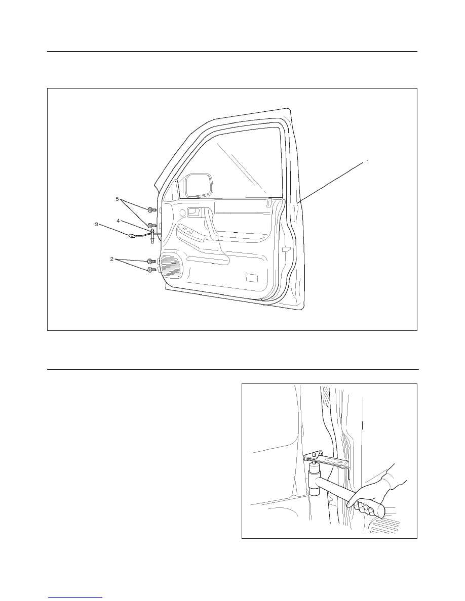
Front Door Assembly
Parts Location
630RW002
Legend
(1) Front Door Assembly
(2) Lower Hinge Bolt
(3) Door Harness Connection
(4) Door Check Arm Pin
(5) Upper Hinge Bolt
Removal
1. Disconnect the battery ground cable.
2. Apply a setting mark on the body side hinge.
3. Remove door check arm pin.
630RW001
Нет комментариевНе стесняйтесь поделиться с нами вашим ценным мнением.
Текст