Isuzu Rodeo UE. Manual — part 174

6E1–67
RODEO X22SE 2.2L ENGINE DRIVEABILITY AND EMISSION
Multiple PCM Information Sensor DTCs Set
Step
Action
Value(s)
Yes
No
1
Was the ”On–Board Diagnostic (OBD) System Check”
performed?
—
Go to
Step 2
Go to
OBD
System
Check
2
1. Turn the ignition OFF, disconnect the PCM.
2. Turn the ignition ON, check the 5 volt reference
circuits for the following conditions:
f
A poor connection at the PCM.
f
An open between the PCM connector and the
splice.
f
A short to ground.
f
A short to voltage.
Is there an open or short?
—
Go to
Step 3
Go to
Step 4
3
Repair the open or short.
Is the action complete?
—
Verify repair
—
4
Check the sensor ground circuit for the following
conditions:
f
A poor connection at the PCM or the affected
sensors.
f
An open between the PCM connector and the
affected sensors.
Is there an open or a poor connection?
—
Go to
Step 5
Go to
Step 6
5
Repair the open or the poor connection.
Is the action complete?
—
Verify repair
—
6
Measure the voltage between the EGR pintle position
sensor signal circuit at the PCM harness connector and
ground.
Does the voltage measure near the specified value?
0 V
Go to
Step 7
Go to
Step 13
7
Measure the voltage between the MAP sensor signal
circuit at the PCM harness connector and ground.
Does the voltage measure near the specified value?
0 V
Go to
Step 8
Go to
Step 14
8
Measure the voltage between the TP sensor signal
circuit at the PCM harness connector and ground.
Does the voltage measure near the specified value?
0 V
Go to
Step 9
Go to
Step 15
9
Measure the voltage between the IAT sensor signal
circuit at the PCM harness connector and ground.
Does the voltage measure near the specified value?
0 V
Go to
Step 10
Go to
Step 16
10
Measure the voltage between the ECT sensor signal
circuit at the PCM harness connector and ground.
Does the voltage measure near the specified value?
0 V
Go to
Step 20
Go to
Step 17
11
Measure the voltage between the A/C Pressure
Sensor circut at the PCM harness connector and
ground.
Does the voltage measure near the specified value?
0 V
Go to
Step 13
Go to
Step 19

6E1–68
RODEO X22SE 2.2L ENGINE DRIVEABILITY AND EMISSION
Multiple PCM Information Sensor DTCs Set
(Cont'd)
Step
No
Yes
Value(s)
Action
12
1. Disconnect the EGR valve.
2. Measure the voltage between the EGR pintle
position sensor signal circuit at the PCM harness
connector and ground.
Does the voltage measure near the specified value?
0 V
Go to
Step 12
Go to
Step 17
13
Replace the EGR valve.
Is the action complete?
—
Verify repair
—
14
Locate and repair the short to voltage in the MAP
sensor signal circuit.
Is the action complete?
—
Verify repair
—
15
Locate and repair the short to voltage in the TP sensor
signal circuit.
Is the action complete?
—
Verify repair
—
16
Locate and repair the short to voltage in the IAT sensor
signal circuit.
Is the action complete?
—
Verify repair
—
17
Locate and repair the short to voltage in the ECT
sensor signal circuit.
Is the action complete?
—
Verify repair
—
18
Locate and repair the short to voltage in the A/C
Pressure Sensor circuit.
Is the action complete?
—
Verify repair
—
19
Locate and repair the short to voltage in the EGR pintle
position sensor signal circuit.
Is the action complete?
—
Verify repair
—
20
Replace the PCM.
IMPORTANT: The replacement PCM must be
programmed. Refer to On–Vehicle Service in
Powertrain Control Module and Sensors for
procedures.
And also refer to latest service bulletin
Check to see if the Latest software is released or not.
And then Down Load the LATEST PROGRAMMED
SOFTWARE to the replacement PCM.
Is the action complete?
—
Go to
OBD
System
Check
—
6E1–69
RODEO X22SE 2.2L ENGINE DRIVEABILITY AND EMISSION
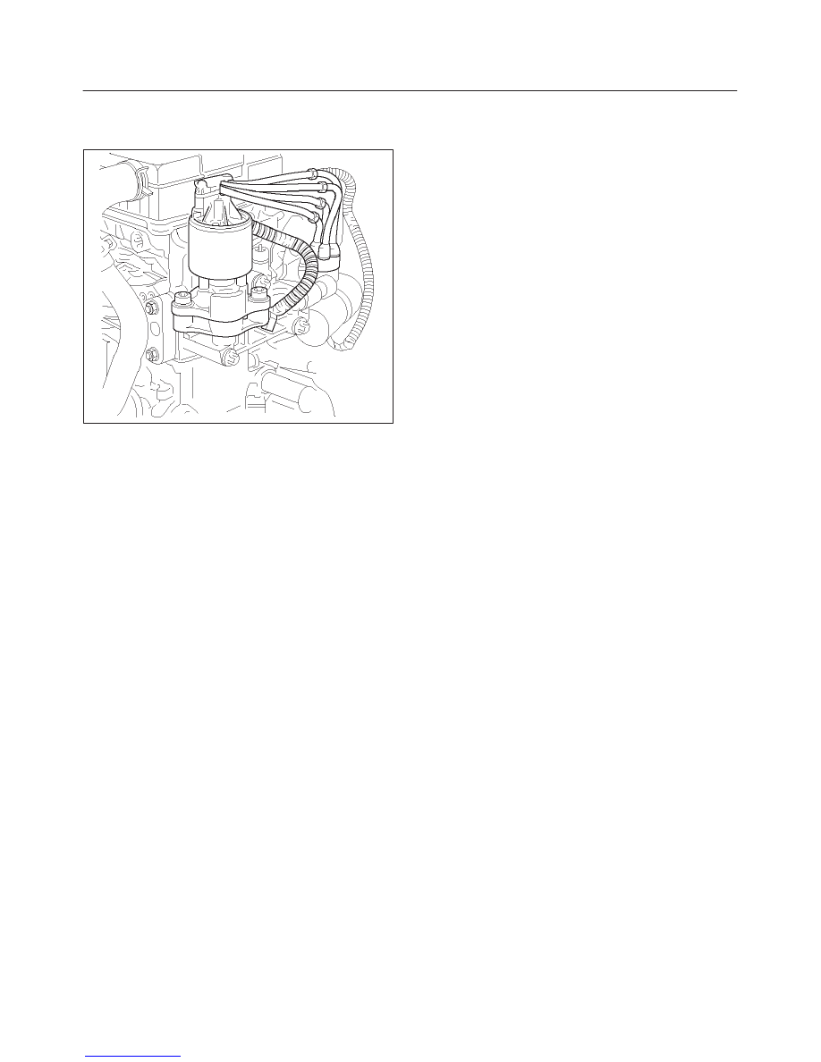
EXHAUST GAS RECIRCULATION
(EGR) DIAGNOSIS
057RX001
An EGR flow check diagnosis of the linear EGR system is
covered by DTC P0401, P0404, and P0405. If EGR
diagnostic trouble code P0401 is encountered, refer to
the DTC charts.
ENGINE Tech 2 DATA DEFINITIONS
AND RANGES
A/C CLUTCH – Tech 2 Displays ON or OFF
Indicates whether the PCM has commanded the A/C
clutch ON. Used in A/C system diagnostics.
A/C REQUEST – Tech 2 Displays YES or NO
Indicates the state of the A/C request input circuit from the
HVAC controls. The PCM uses the A/C request signal to
determine whether A/C compressor operation is being
requested.
AIR/FUEL RATIO – Tech 2 Range 0.0–25.5
Air/fuel ratio indicates the PCM commanded value. In
”Closed Loop”, the air/fuel ratio should normally be
displayed around ”14.2–14.7.” A lower air/fuel ratio
indicates a richer commanded mixture, which may be
seen during power enrichment or TWC protection modes.
A higher air/fuel ratio indicates a leaner commanded
mixture. This can be seen during deceleration fuel mode.
BARO kPa – Tech 2 Range 10–105 kPa/0.00–5.00
Volts
The barometric pressure reading is determined from the
MAP sensor signal monitored during key up and wide
open throttle (WOT) conditions. The barometric pressure
is used to compensate for altitude differences and is
normally displayed around ”61–104” depending on
altitude and barometric pressure.
CMP ACT. COUNTER – Cam Position Activity
DECEL FUEL MODE – Tech 2 Displays ACTIVE or
INACTIVE
”ACTIVE” displayed indicates that the PCM has detected
conditions appropriate to operate in deceleration fuel
mode. The PCM will command the deceleration fuel
mode when it detects a closed throttle position while the
vehicle is traveling over 20 mph. While in the deceleration
fuel mode, the PCM will decrease the amount of fuel
delivered by entering ”Open Loop” and decreasing the
injector pulse width.
DESIRED EGR POS. – Tech 2 Range 0%–100%
Represents the EGR pintle position that the PCM is
commanding.
DESIRED IDLE – Tech 2 Range 0–3187 RPM
The idle speed that the PCM is commanding. The PCM
will compensate for various engine loads based on engine
coolant temperature, to keep the engine at the desired
speed.
ECT – (Engine Coolant Temperature) Tech 2 Range
–40
°
C to 151
°
C (–40
°
F to 304
°
F)
The engine coolant temperature (ECT) is mounted in the
coolant stream and sends engine temperature
information to the PCM. The PCM applies 5 volts to the
ECT sensor circuit. The sensor is a thermistor which
changes internal resistance as the temperature changes.
When the sensor is cold (high resistance), the PCM
monitors a high signal voltage and interprets that as a cold
engine. As the sensor warms (decreasing resistance),
the voltage signal will decrease and the PCM will interpret
the lower voltage as a warm engine.
EGR DUTY CYCLE – Tech 2 Range 0%–100%
Represents the EGR valve driver PWM signal from the
PCM. A duty cycle of 0% indicates that no EGR flow is
being commanded; a 100% duty cycle indicates
maximum EGR flow commanded.
EGR FEEDBACK – Tech 2 Range 0.00–5.00 Volts
Indicates the EGR pintle position sensor signal voltage
being monitored by the PCM. A low voltage indicates a
fully extended pintle (closed valve); a voltage near 5 volts
indicates a retracted pintle (open valve).
EGR TEST COUNT – Tech 2 Range 0–255
Indicates the number of EGR flow test samples collected
during the current ignition cycle. Under normal operation,
only one sample is allowed during an ignition cycle. If the
PCM battery feed has been disconnected or a DTC
P0401 has been cleared, 10 EGR flow test samples will
be allowed during the ignition cycle. This is to allow repair
verification during a single ignition cycle.
ENGINE LOAD – Tech 2 Range 0%–100%
Engine load is calculated by the PCM from engine speed
and MAP sensor readings. Engine load should increase
with an increase in RPM or air flow.
ENGINE RUN TIME – Tech 2 Range 00:00:00–
99:99:99 Hrs:Min:Sec
Indicates the time elapsed since the engine was started.
If the engine is stopped, engine run time will be reset to
00:00:00.
ENGINE SPEED – Range 0–9999 RPM
Engine speed is computed by the PCM from the 58X
reference input. It should remain close to desired idle
under various engine loads with engine idling.
6E1–70
RODEO X22SE 2.2L ENGINE DRIVEABILITY AND EMISSION
EVAP PURGE PWM – Tech 2 Range 0%–100%
Represents the PCM commanded PWM duty cycle of the
EVAP purge solenoid valve. ”0%” displayed indicates no
purge; ”100%” displayed indicates full purge.
EVAP VACUUM SWITCH – Tech 2 Displays PURGE
or NO PURGE
The EVAP purge vacuum switch is a normally closed
switch positioned in the purge line between the canister
and the EVAP purge solenoid. The EVAP purge vacuum
switch will open when vacuum increases to greater than
5 inches of water in the purge line. The EVAP purge
vacuum switch is used by the PCM to monitor EVAP
canister purge solenoid operation and purge system
integrity. The EVAP purge vacuum switch should be
closed to ground with no vacuum present (0% EVAP
purge PWM). With EVAP purge PWM at 25% or greater,
the EVAP purge vacuum switch should be open and
”PURGE” should be indicated.
FUEL PUMP – Tech 2 Displays ON or OFF
Indicates the PCM commanded state of the fuel pump
relay driver circuit.
FUEL TRIM CELL – Tech 2 Range 0–21
The fuel trim cell is dependent upon engine speed and
MAF sensor readings. A plot of RPM vs. MAF is divided
into 22 cells. Fuel trim cell indicates which cell is currently
active.
FUEL TRIM LEARN – Tech 2 Displays NO or YES
When conditions are appropriate for enabling long term
fuel trim corrections, fuel trim learn will display YES. This
indicates that the long term fuel trim is responding to the
short term fuel trim. If the fuel trim learn displays NO, then
long term fuel trim will not respond to changes in short
term fuel trim.
GENERATOR CONTROL – Tech 2 Displays ACTIVE
or INACTIVE.
HO2S BANK 1, SEN. 1 – Tech 2 Range 0–1000 mV
Represents the fuel control exhaust oxygen sensor
output voltage. Should fluctuate constantly within a range
between 10 mV (lean exhaust) and 1000 mV (rich
exhaust) while operating in ”Closed Loop”.
HO2S BANK 1, SEN. 2 – Tech 2 Range 0–1000 mV
Represents the exhaust oxygen sensor output voltage.
Should fluctuate constantly within a range between 10
mV (lean exhaust) and 1000 mV (rich exhaust) while
operating in ”Closed Loop”. This is used along with HO2S
Bank 1, Sensor 3 to determine the catalytic converter
efficiency in the manual transmission models.
HO2S BANK 1, SEN. 1 – Tech 2 Displays NOT
READY or READY
Indicates the status of the exhaust oxygen sensor. The
Tech 2 will indicate that the exhaust oxygen sensor is
ready when the PCM detects a fluctuating HO2S voltage
sufficient to allow ”Closed Loop” operation. This will not
occur unless the exhaust sensor is warmed up.
HO2S WARM UP TIME BANK 1, SEN. 1 – Tech 2
Range 00:00:00–99:99:99 HRS:MIN:SEC
Indicates warm–up time for each HO2S. The HO2S
warm–up time is used for the HO2S heater test. The PCM
will run the heater test only after a cold start (determined
by engine coolant and intake air temperature at the time
of start–up) and only once during an ignition cycle. When
the engine is started the PCM will monitor the HO2S
voltage. When the HO2S voltage indicates a sufficiently
active sensor, the PCM looks at how much time has
elapsed since start–up. If the PCM determines that too
much time was required for the HO2S to become active,
a DTC will set. If the engine was warm when started,
HO2S warm–up will display ”00:00:00.”
IAC POSITION – Tech 2 Range 0–255 Counts
Displays the commanded position of the idle air control
pintle in counts. A larger number of counts means that
more air is being commanded through the idle air
passage. Idle air control should respond fairly quickly to
changes in engine load to maintain desired idle RPM.
IAT (INTAKE AIR TEMPERATURE) – Tech 2 Range
–40
°
C to 151
°
C (–40
°
F to 304
°
F)
The PCM converts the resistance of the intake air
temperature sensor to degrees. Intake air temperature
(IAT) is used by the PCM to adjust fuel delivery and spark
timing according to incoming air density.
IGNITION 1 – Tech 2 Range 0–25.5 Volts
This represents the system voltage measured by the
PCM at its ignition feed.
INJ. PULSE BANK 1 – Tech 2 Range 0–1000 msec.
Indicates the amount of time the PCM is commanding
each injector ON during each engine cycle. A longer
injector pulse width will cause more fuel to be delivered.
Injector pulse width should increase with increased
engine load.
LONG TERM FUEL TRIM BANK 1
The long term fuel trim is derived from the short term fuel
trim values and represents a long term correction of fuel
delivery for the bank in question. A value of 0% indicates
that the fuel delivery requires no compensation to
maintain the PCM commanded air/fuel ratio. A negative
value significantly below 0% indicates that the fuel
system is rich and fuel delivery is being reduced
(decreased injector pulse width). A positive value
significantly greater than 0% indicates that a lean
condition exists and the PCM is compensating by adding
fuel (increased injector pulse width). Because long term
fuel trim tends to follow short term fuel trim, a value in the
negative range due to canister purge at idle should not be
considered unusual. Fuel trim values at maximum
authority may indicate an excessively rich or lean system.
LOOP STATUS – Tech 2 Displays OPEN or CLOSED
”CLOSED” indicates that the PCM is controlling fuel
delivery according to oxygen sensor voltage. In ”OPEN”
the PCM ignores the oxygen sensor voltage and bases
the amount of fuel to be delivered on TP sensor, engine
coolant, and MAF sensor inputs only.
Нет комментариевНе стесняйтесь поделиться с нами вашим ценным мнением.
Текст