Isuzu Rodeo UE. Manual — part 173

6E1–63
RODEO X22SE 2.2L ENGINE DRIVEABILITY AND EMISSION
Injector Coil Test Procedure (Steps 1–6) And Injector Balance Test Procedure
(Steps 7–11)
(Cont'd)
Step
No
Yes
Value(s)
Action
5
1. Set the injector switch box to injector #1.
2. Press the ”Push to Start Test” button on the fuel
injector tester.
3. Observe the voltage reading on the DVM.
IMPORTANT: The voltage reading may rise during the
test.
4. Record the lowest voltage observed after the first
second of the test.
5. Set the injector switch box to the next injector and
repeat steps 2, 3, and 4.
Did any fuel injector have an erratic voltage reading
(large fluctuations in voltage that did not stabilize) or a
voltage reading above the specified value?
9.5 V
Go to
Step 4
Go to
Step 6
6
1. Identify the highest voltage reading recorded (other
than those above 9.5 V).
2. Subtract the voltage reading of each injector from
the highest voltage selected in step 1. Repeat until
you have a subtracted value for each injector.
For any injector, is the subtracted value in step 2
greater than the specified value?
0.6 V
Go to
Step 4
Go to
Step 7
7
CAUTION: In order to reduce the risk of fire and
personal injury, wrap a shop towel around the
fuel pressure connection. The towel will absorb
any fuel leakage that occurs during the
connection of the fuel pressure gauge. Place the
towel in an approved container when the
connection of the fuel pressure gauge is
complete.
1. Connect the J 34730–1 Fuel Pressure Gauge to the
fuel pressure test port.
2. Energize the fuel pump using the Tech 2.
3. Place the bleed hose of the fuel pressure gauge into
an approved gasoline container.
4. Bleed the air out of the fuel pressure gauge.
5. With the fuel pump running, observe the reading on
the fuel pressure gauge.
Is the fuel pressure within the specified values?
296 kPa– 376
kPa (43–55
psi)
Go to
Step 8
Go to
Fuel
System
Diagnosis
8
Turn the fuel pump OFF.
Does the fuel pressure remain constant?
—
Go to
Step 9
Go to
Fuel
System
Diagnosis
6E1–64
RODEO X22SE 2.2L ENGINE DRIVEABILITY AND EMISSION
Injector Coil Test Procedure (Steps 1–6) And Injector Balance Test Procedure
(Steps 7–11)
(Cont'd)
Step
No
Yes
Value(s)
Action
9
1. Connect the J 39021–5V Fuel Injector Tester and
J39021–90 Injector Switch Box to the fuel injector
harness connector.
2. Set the amperage supply selector switch on the fuel
injector tester to the ”Balance Test” 0.5–2.5 amp
position.
3. Using the Tech 2 turn the fuel pump ON then OFF in
order to pressurize the fuel system.
4. Record the fuel pressure indicated by the fuel
pressure gauge after the fuel pressure stabilizes.
This is the first pressure reading.
5. Energize the fuel injector by depressing the Push to
Start Test button on the fuel injector tester.
6. Record the fuel pressure indicated by the fuel
pressure gauge after the fuel pressure gauge
needle has stopped moving. This is the second
pressure reading.
7. Repeat steps 1 through 6 for each fuel injector.
8. Subtract the second pressure reading from the first
pressure reading for one fuel injector. The result is
the pressure drop value.
9. Obtain a pressure drop value for each fuel injector.
10.Add all of the individual pressure drop values. This
is the total pressure drop.
11. Divide the total pressure drop by the number of fuel
injectors. This is the average pressure drop.
Does any fuel injector have a pressure drop value that
is either higher than the average pressure drop or lower
than the average pressure drop by the specified value?
10 kPa (1.5
psi)
Go to
Step 10
Go to
OBD
System
Check
10
Re–test any fuel injector that does not meet the
specification. Refer to the procedure in step 11.
NOTE: Do not repeat any portion of this test before
running the engine in order to prevent the engine from
flooding.
Does any fuel injector still have a pressure drop value
that is either higher than the average pressure drop or
lower than the average pressure drop by the specified
value?
10 kPa (1.5
psi)
Go to
Step 11
Go to
Symptoms
11
Replace the faulty fuel injector(s). Refer to Fuel
Injector.
Is the action complete?
—
Verify repair
—
6E1–65
RODEO X22SE 2.2L ENGINE DRIVEABILITY AND EMISSION
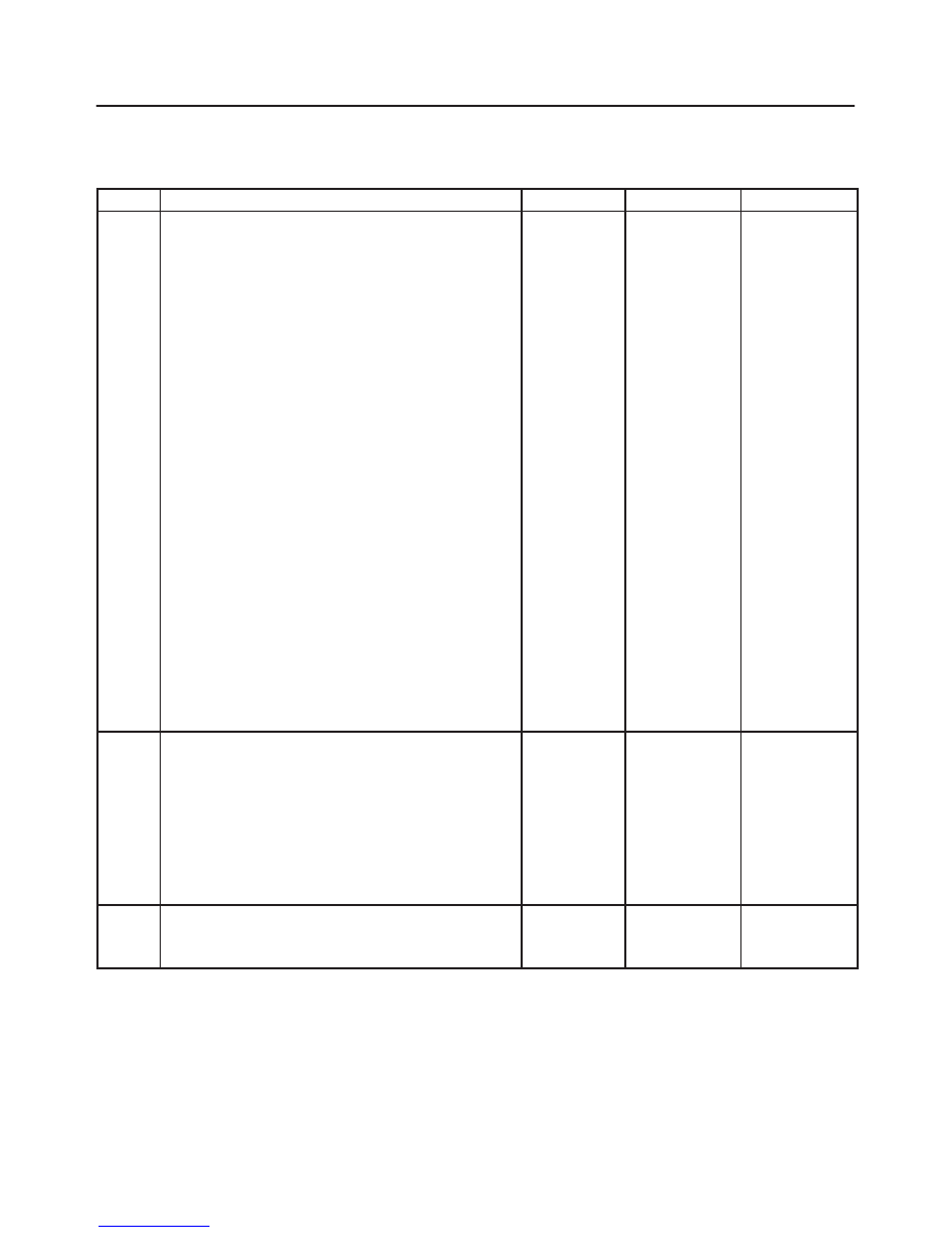
POWERTRAIN CONTROL MODULE
(PCM) DIAGNOSIS
014RX002
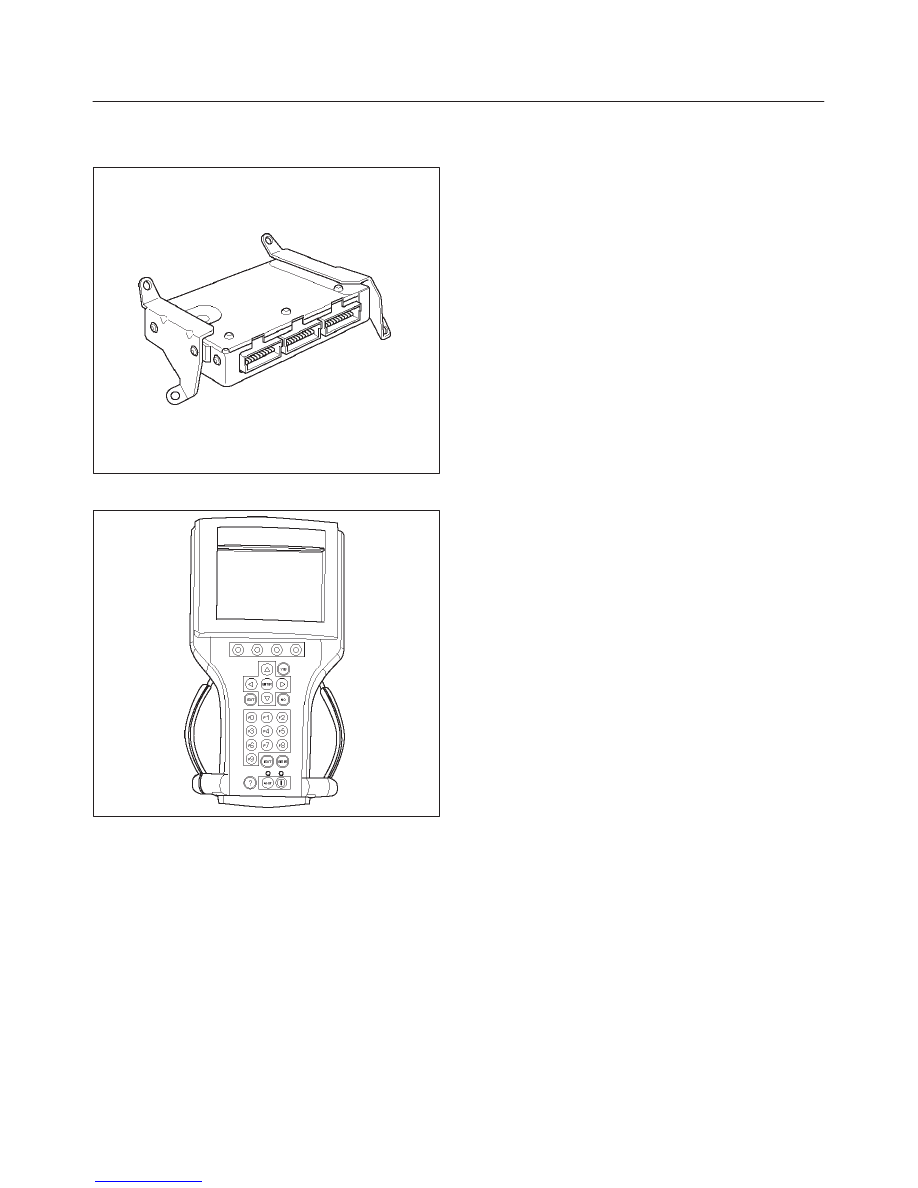
To read and clear diagnostic trouble codes, use a Tech 2.
901RX031
IMPORTANT:
Use of a Tech 2 is recommended to clear
diagnostic trouble codes from the PCM memory.
Diagnostic trouble codes can also be cleared by turning
the ignition OFF and disconnecting the battery power
from the PCM for 30 seconds. Turning off the ignition and
disconnecting the battery power from the PCM will cause
all diagnostic information in the PCM memory to be
cleared. Therefore, all the diagnostic tests will have to be
re–run.
Since the PCM can have a failure which may affect only
one circuit, following the diagnostic procedures in this
section will determine which circuit has a problem and
where it is.
If a diagnostic chart indicates that the PCM connections
or the PCM is the cause of a problem, and the PCM is
replaced, but this does not correct the problem, one of the
following may be the reason:
f
There is a problem with the PCM terminal
connections. The terminals may have to be removed
from the connector in order to check them properly.
f
EEPROM program is not correct for the application.
Incorrect components or reprogramming the PCM
with the wrong EEPROM program may cause a
malfunction and may or may not set a DTC.
f
The problem is intermittent. This means that the
problem is not present at the time the system is being
checked. In this case, make a careful physical
inspection of all components and wiring associated
with the affected system and refer to the Symptoms
portion of the manual.
f
There is a shorted solenoid, relay coil, or harness.
Solenoids and relays are turned ON and OFF by the
PCM using internal electronic switches called drivers.
A shorted solenoid, relay coil, or harness will not
damage the PCM but will cause the solenoid or relay
to be inoperative.
MULTIPLE PCM INFORMATION
SENSOR DTCs SET
Circuit Description
The powertrain control module (PCM) monitors various
sensors to determine the engine operating conditions.
The PCM controls fuel delivery, spark advance, and
emission control device operation based on the sensor
inputs.
The PCM provides a sensor ground to all of the sensors.
The PCM applies 5 volts through a pull–up resistor, and
determines the status of the following sensors by
monitoring the voltage present between the 5–volt supply
and the resistor:
f
The Fuel Tank Vapor Pressure Sensor
f
The throttle position (TP) sensor
f
The manifold absolute pressure (MAP) sensor
The PCM provides the following sensors with a 5–volt
reference and a sensor ground signal:
f
The Linear exhaust gas recirculation (EGR) valve
f
The A/C Pressure Sensor
The PCM monitors the separate feedback signals from
these sensors in order to determine their operating
status.
Diagnostic Aids
Be sure to inspect PCM and engine grounds for being se-
cure and clean.
A short to voltage in one of the sensor input circuits may
cause one or more of the following DTCs to be set:
f
P0108/P1106
f
P0113/P1111
f
P0118/P1115
f
P0123/P1121
f
P0463
If a sensor input circuit has been shorted to voltage, en-
sure that the sensor is not damaged. A damaged sensor
6E1–66
RODEO X22SE 2.2L ENGINE DRIVEABILITY AND EMISSION
will continue to indicate a high or low voltage after the af-
fected circuit has been repaired. If the sensor has been
damaged, replace it.
An open in the sensor ground circuit between the PCM
and the splice will cause one or more of the following
DTCs to be set:
f
P0108/P1106
f
P0113/P1111
f
P0118/P1115
f
P0123/P01121
f
P0453/P0463
A short to ground in the 5–volt reference A circuit will
cause one or more of the following DTCs to be set:
f
P0107/P1107
f
P0122/P1122
f
P0112/P1112
f
P0117/P1114
f
P0454/P0462
f
P0405
f
P0532
Check for the following conditions:
f
Poor connection at PCM. Inspect the harness
connectors for backed–out terminals, improper
mating, broken locks, improperly formed or damaged
terminals, and a poor terminal–to–wire connection.
f
Damaged harness. Inspect the wiring harness for
damage. If the harness is not damaged, observe an
affected sensor’s displayed value on the Tech 2 with
the ignition ON and the engine OFF while you move
the connectors and the wiring harnesses related to
the following sensors:
f
IAT
f
ECT
f
TP
f
MAP
f
EGR
f
Fuel Tank Vapor Pressure Sensor
f
A/C Pressure Sensor
Нет комментариевНе стесняйтесь поделиться с нами вашим ценным мнением.
Текст