Isuzu Rodeo UE. Manual — part 505
7B–52
MANUAL TRANSMISSION
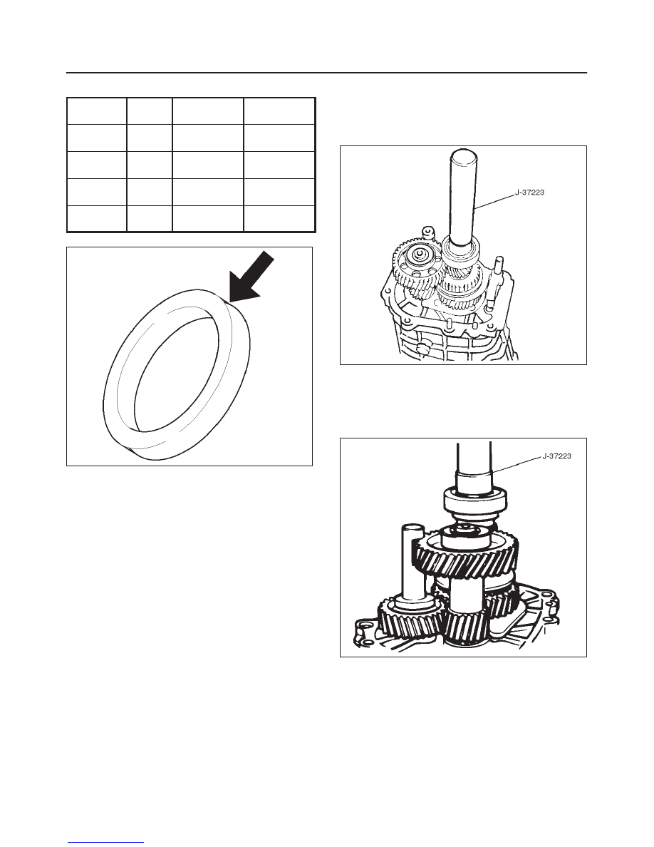
Thrust Washer Availability
Thickness
mm (in)
Color
Coding
A mm (in)
Clearance
mm (in)
7.9 (0.311)
White
8.05–8.1
(0.317–0.319)
0.15–0.25
(0.006–0.010)
8.0 (0.315)
Yellow
8.1–8.2
(0.319–0.323)
0.1–0.25
(0.004–0.010)
8.1 (0.319)
Green
8.2–8.3
(0.323–0.327)
0.1–0.25
(0.004–0.010)
8.2 (0.323)
Bluen
8.3–8.36
(0.327–0.329)
0.1–0.21
(0.004–0.008)
226RS024
f
Apply grease to the thrust washer and the lock ball.
f
Install the thrust washer and the lock ball.
17. Install thrust plate(8) and retainer(7).
18. Install retaining snap ring(6), clip(5), speedometer
drive gear(4), and bearing snap ring(3). (4X2)
19. Use the installer J–37223 to install the ball bearing(2)
to the mainshaft. (4X2)
226RS096
20. Install bearing snap ring(1). (4X2)
21. Apply engine oil to the bearing inner and outer
circumference. (4X4)
Use the installer J–37223 to install the ball bearing(2)
to the mainshaft in proper direction. (4X4)
226RS025
22. Install oil seal collar(1). (4X4)
MANUAL TRANSMISSION
7B–53
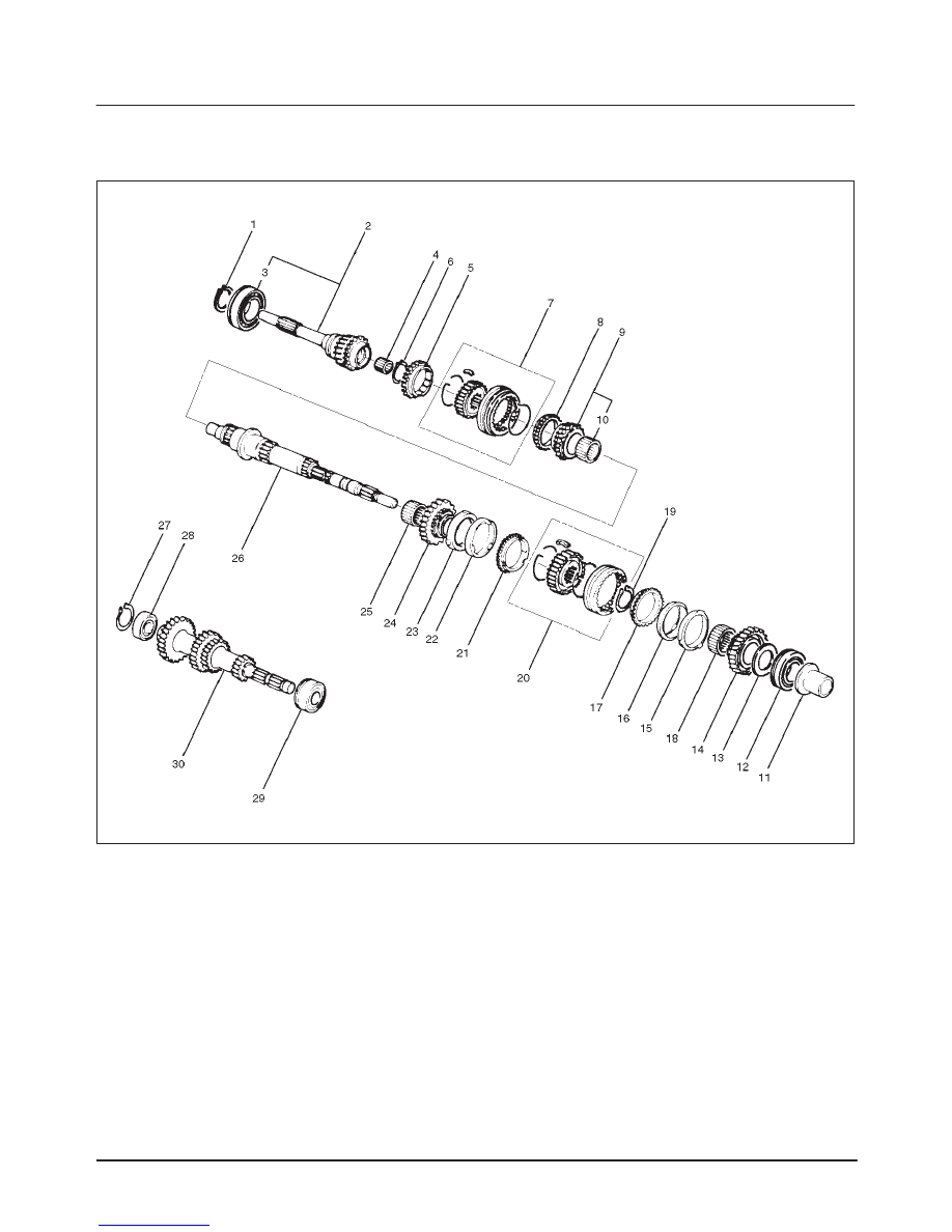
Top Gear Shaft, Main Gear Shaft, and Counter Gear Shaft (MUA)
Disassmebled View
226RS026
Legend
(1) Top Gear Shaft Snap Ring
(2) Top Gear Shaft
(3) Ball Bearing
(4) Needle Bearing
(5) Top Block Ring
(6) Mainshaft Snap Ring
(7) 3rd–4th Synchronizer Assembly
(8) 3rd Block Ring
(9) 3rd Gear
(10) Needle Bearing
(11) Needle Bearing Collar
(12) Mainshaft Ball Bearing
(13) 1st Gear Thrust Bearing
(14) 1st Gear
(15) 1st Inside Ring
(16) 1st Outside Ring
(17) 1st Block Ring
(18) Needle Bearing
(19) Clutch Hub Snap Ring
(20) 1st–2nd Synchronizer Assembly
(21) 2nd Block Ring
(22) 2nd Outside Ring
(23) 2nd Inside Ring
(24) 2nd Gear
(25) Needle Bearing
(26) Mainshaft
(27) Bearing Snap Ring
(28) Front Rollar Bearing
(29) Center Roller Bearing
(30) Counter Gear Shaft
7B–54
MANUAL TRANSMISSION
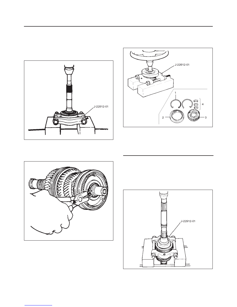
Disassembly
1. Use a pair of snap ring pliers to remove the top gear
shaft snap ring(1).
2. Remove top gear shaft(2) with ball bearing(3).
3. Use a bench press and the bearing remover
J–22912–01 to remove the ball bearing(3).
226RS027
4. Remove needle bearing(4) and top block ring(5),
mainshaft snap ring.
5. Use a pair of snap ring pliers to remove the mainshaft
snap ring(6).
226RS028
6. Use a bench press and the bearing remover
J–22912–01 to remove the 3rd–4th synchronizer
assembly(7) as a set.
Disassemble the synchronizer assembly.
226RS029
Legend
(1) Springs
(2) Sleeve
(3) Clutch Hub
(4) Inserts
7. Remove 3rd block ring(8), 3rd gear(9), and needle
bearing(10).
8. Remove needle bearing collar(11).
9. Use a bench press and the bearing remover
J–22912–01 to remove the 1st gear(14) together with
the mainshaft ball bearing(12) and 1st gear thrust
bearing(13).
226RS030

MANUAL TRANSMISSION
7B–55
10. Disassemble 1st inside ring(15), 1st outside ring(16),
and 1st block ring(17).
11. Remove needle bearing(18).
12. Use a pair of snap ring pliers to remove the clutch hub
snap ring(19).
226RS031
13. Use a bench press and the bearing remover
J–22912–01 to remove the 2nd gear(24) together
with 1st–2nd synchronizer assembly(20), 2nd block
ring(21), 2nd outside ring(22), and 2nd inside
ring(23).
Disassemble the synchronizer assembly.
226RW147
Legend
(1) Springs
(2) Sleeve
(3) Clutch Hub
(4) Inserts
14. Remove needle bearing(25) from mainshaft(26).
15. Remove bearing snap ring(27)
16. Use a bench press and the bearing remover
J–22912–01 to remove the front roller bearing(28).
226RS034
17. Remove center roller bearing(29) from counter gear
shaft(30).
Inspection and Repair
Make the necessary adjustments, repairs, and part
replacements if excessive wear or damage is discovered
during inspection.
Block Ring and Dog Teeth Clearance
f
Use a thickness gauge to measure the clearance
between the block ring and the dog teeth.
226RS035
If the measured value exceeds the specified limit, the
block ring must be replaced.
Block Ring and Dog Teeth Clearance
Standard
Limit
1.5 mm (0.059 in)
0.8 mm (0.032 in)
Нет комментариевНе стесняйтесь поделиться с нами вашим ценным мнением.
Текст