Isuzu Rodeo UE. Manual — part 506
7B–56
MANUAL TRANSMISSION
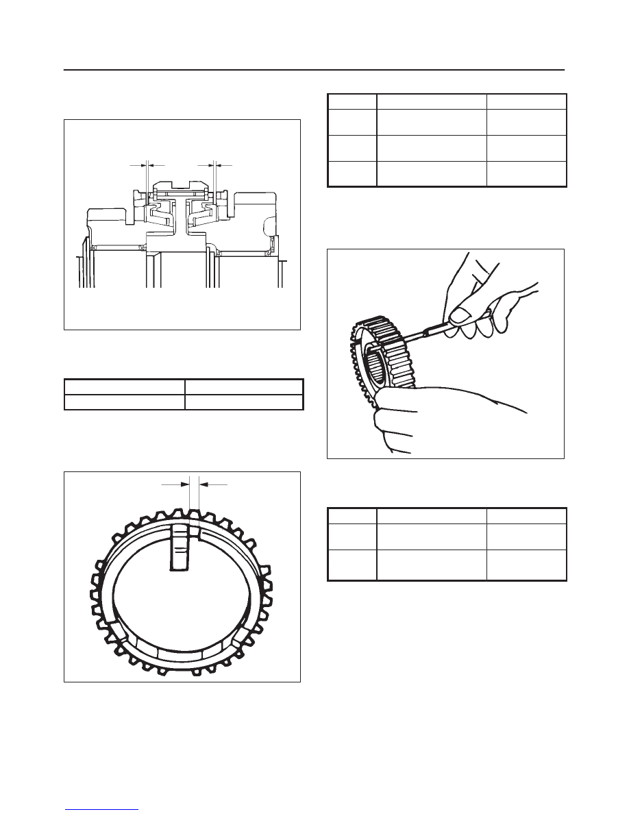
1st–2nd Synchronizer (3–CONE)
f
Use a thickness gauge to measure the clearance
between the block ring and the dog teeth.
226RS036
If the measured value exceeds the specified limit,the
1st–2nd synchronizer assembly must be replaced.
Block Ring and Dog Teeth Clearance
Standard
Limit
1.5 mm (0.059 in)
0.8 mm (0.032 in)
Block Ring and Insert Clearance
f
Use a vernier caliper or thickness gauge to measure
the clearance between the block ring and the insert.
226RS037
If the measured value exceeds the specified limit, the
block ring and the insert must be replaced.
Block and Insert Clearance
Standard
Limit
3rd–4th
3.46 – 3.74 mm
(0.136 – 0.147 in)
4.0 mm
(0.158 in)
1st–2nd
4.34 – 4.66 mm
(0.171 – 0.183 in)
4.9 mm
(0.193 in)
Rev–5th
3.59 – 3.91 mm
(0.141 – 0.154 in)
4.1 mm
(0.161 in)
Clutch Hub and Insert Clearance
f
Use a thickness gauge to measure the clearance
between the clutch hub and the insert.
226RS038
If the measured value exceeds the specified limit, the
clutch hub and the insert must be replaced.
Clutch Hub and Insert Clearance
Standard
Limit
3rd–4th
0.01 – 0.19 mm
(0.0004 – 0.0075 in)
0.3 mm
(0.012 in)
1st–2nd
0.09 – 0.31 mm
0.4 mm
Rev–5th
(0.0035 – 0.0122 in)
(0.016 in)
MANUAL TRANSMISSION
7B–57
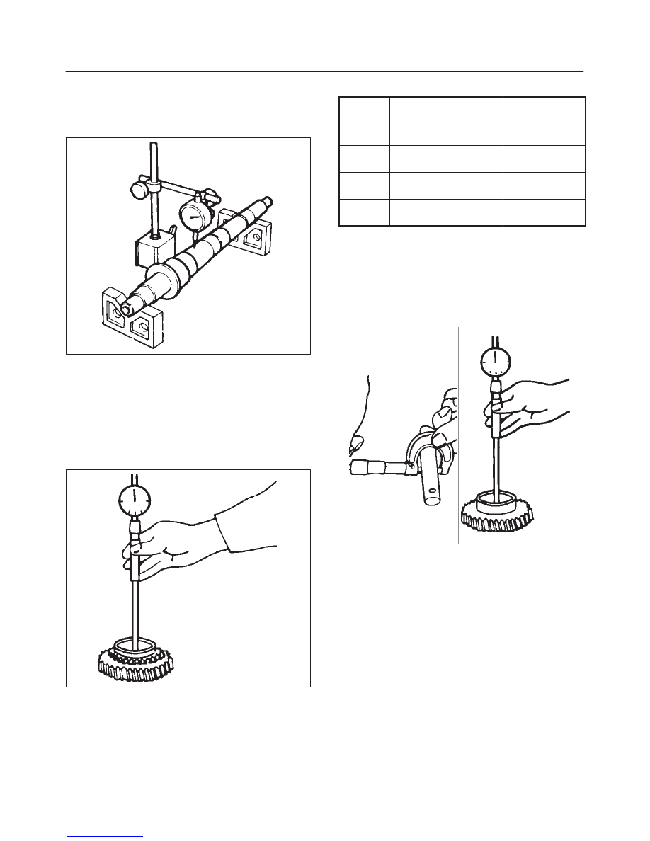
Mainshaft Run-out
f
Install the mainshaft to V-blocks.
f
Use a dial indicator to measure the mainshaft central
portion run-out.
226RS039
If the measured mainshaft run-out exceeds the
specified limit, the mainshaft must be replaced.
Mainshaft Run–out
Limit: 0.05 mm (0.0020 in)
Gear Inside Diameter
f
Use an inside dial indicator to measure the gear inside
diameter.
226RS040
If the measured value is less than the specified limit,
the gear must be replace.
Gear Inside Diameter
Standard
Limit
1st
45.000 – 45.013 mm
45.100 mm
3rd
(1.771 – 1.772 in)
(1.776 in)
2nd
52.000 – 52.013 mm
(2.047 – 2.048 in)
52.100 mm
(2.051 in)
Rev.
48.000 – 48.013 mm
(1.889 – 1.890 in)
48.100 mm
(1.894 in)
5th
32.000 – 32.013 mm
(1.259 – 1.260 in)
32.100 mm
(1.246 in)
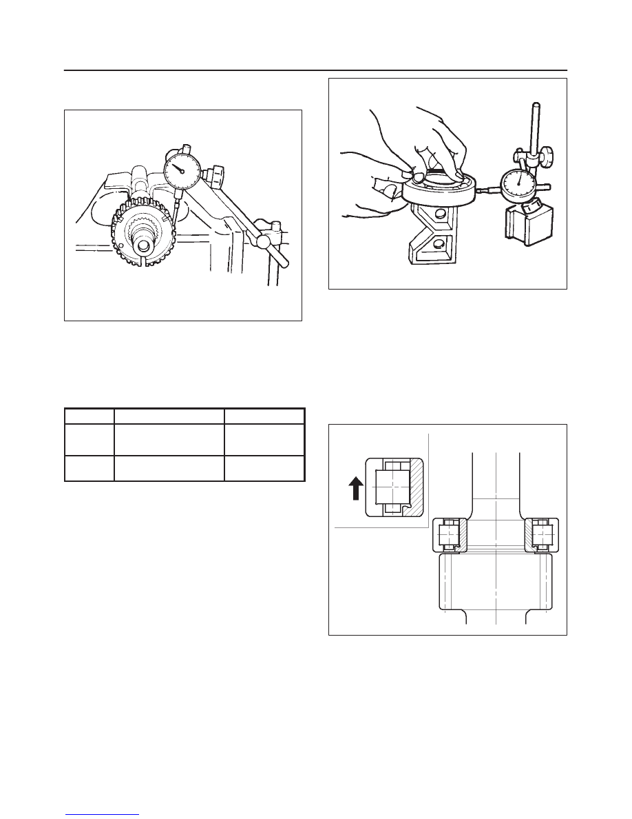
Reverse Idler Gear and Idler Gear Shaft
Clearance
f
Use a micrometer to measure the idler gear shaft
diameter.
f
Use an inside dial indicator to measure the idler gear
inside diameter.
226RS041
f
Calculate the idler gear and idler gear shaft
clearance.
Idler gear inside diameter-idler gear shaft diameter =
idle gear and idler gear shaft clearance.
If the measured value exceeds the specified limit, the
idle gear and/or the idler gear shaft must be replaced.
Idler Gear and Idler Gear Shaft Clearance
Standard: 0.041–0.074 mm (0.016–0.0029 in)
Limit: 0.150 mm (0.0059 in)
7B–58
MANUAL TRANSMISSION
Clutch Hub Spline Play
f
Set a dial indicator to the clutch hub to be measured.
226RS042
f
Move the clutch hub as far as possible to both the right
and the left.
Note the dial indicator reading.
If the measured value exceeds the specified limit, the
clutch hub must be replaced.
Clutch Hub Spline Play
Standard
Limit
1st–2nd
0 – 0.1 mm
0.2 mm
3rd–4th
(0 – 0.004 in)
(0.008 in)
Rev. 5th
0 – 0.2 mm
(0 – 0.008 in)
0.3 mm
(0.012 in)
Ball Bearing Play
f
Use a dial indicator to measure the ball bearing play.
Ball Bearing Play
Limit: 0.2 mm (0.008 in)
226RS043
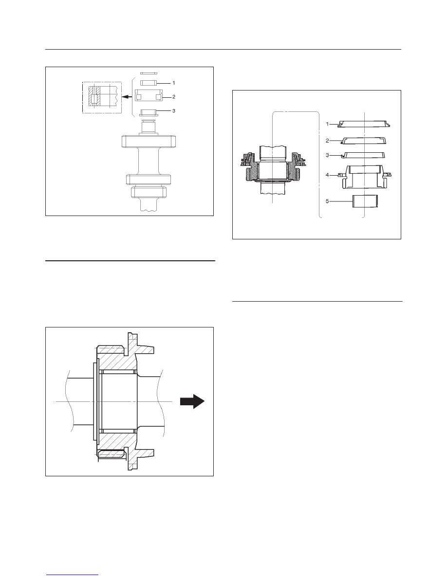
Reassembly
1. Install center roller bearing(29) to counter gear
shaft(30).
f
Apply engine oil to the bearing inner and outer
circumferences.
f
Install the roller bearing in the proper direction.
NOTE: Check that outer race moves only in the direction
of arrow.
226RS044
2. Install front roller bearing(28) by performing the
following steps.
f
Use bearing installer to install the front roller
bearing inner race to the counter gear shaft.
f
Install the outer race and roller assembly.
The snap ring groove must be facing the
transmission front side.
MANUAL TRANSMISSION
7B–59
f
Use bearing installer J–35283 to install the ring.
226RS045
Legend
(1) Ring
(2) Outer Race and Roller Assembly
(3) Inner Race
3. Install bearing snap ring(27) to mainshaft(26).
4. Apply engine oil to the needle bearing(25) and the 2nd
gear thrust surfaces.
Install the needle bearing(25) and the 2nd gear(24) to
the mainshaft.
The 2nd gear dog teeth must be facing the
transmission rear side.
226RS046
5. Assemble 2nd inside ring(23), 2nd outside ring(22),
and 2nd block ring(21).
f
Apply engine oil to the synchronizer ring friction
surfaces.
226RS047
Legend
(1) Block Ring
(2) Outside Ring
(3) Inside Ring
(4) 2nd Gear
(5) Needle Bearing
6. Assemble 1st–2nd synchronizer assembly by
performing the following steps:
1. Check that the inserts(3) fit snugly into the block
ring insert grooves.
2. Check that the inserts springs(4) are fitted to the
inserts as shown in the illustration.
3. Check that the clutch hub(5) and the sleeve(6)
slide smoothly.
4. Install the synchronizer assembly to the
mainshaft.
The clutch hub face (with the heavy boss) must be
facing the 2nd gear side.
Нет комментариевНе стесняйтесь поделиться с нами вашим ценным мнением.
Текст