Isuzu Rodeo UE. Manual — part 432
6E2–483
RODEO 6VD1 3.2L ENGINE DRIVEABILITY AND EMISSIONS
Installation Procedure
1. Install the rubber grommet on the fuel pump
assembly.
014RW133
2. Install the fuel tank vapor pressure sensor on the fuel
pump assembly.
f
Insert the sensor nipple firmly into the grommet.
f
Keep twisting and pushing the sensor until the wide
portion of the nipple shows on the other side of the
grommet.
3. Install the fuel pump assembly on the fuel tank. Refer
to
Fuel Tank In Fuel Pump..
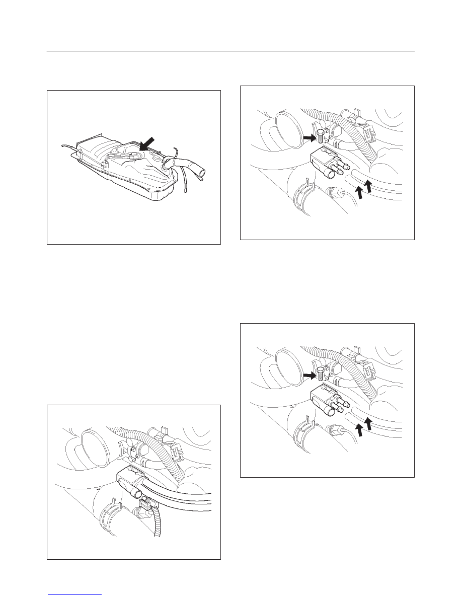
EVAP Canister Purge Solenoid
Removal Procedure
1. Disconnect the electrical connector from the EVAP
canister purge solenoid.
2. Disconnect the vacuum hoses from the EVAP
canister purge solenoid.
014RW136
3. Remove the EVAP canister purge solenoid retaining
bolt from the upper intake manifold.
4. Remove the EVAP canister purge solenoid.
014RW137
Installation Procedure
1. Install the EVAP canister purge solenoid on the upper
intake manifold.
2. Install the EVAP canister purge solenoid retaining
bolt.
3. Connect the vacuum hoses to the EVAP canister
purge solenoid.
014RW137
6E2–484
RODEO 6VD1 3.2L ENGINE DRIVEABILITY AND EMISSIONS
4. Connect the electrical connector to the EVAP canister
purge solenoid.
014RW138
Fuel Tank Vent Valve
Removal and Installation Procedure
Refer to
Fuel Pump
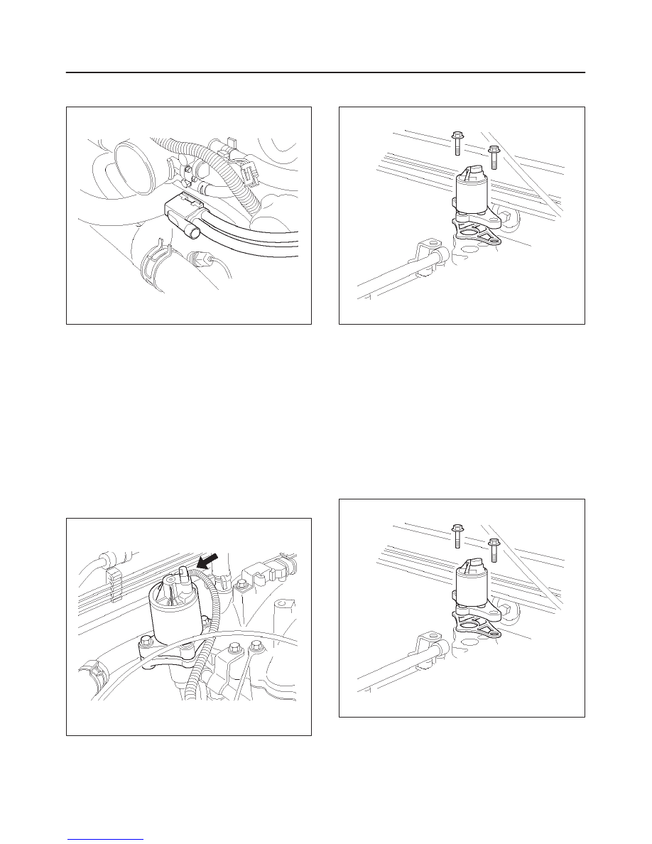
Linear Exhaust Gas Recircula-
tion (EGR) Valve
Removal Procedure
1. Disconnect the negative battery cable.
2. Disconnect the electrical connector at the EGR valve.
014RW139
3. Remove the bolt and the nut from the upper intake
manifold.
014RW098
4. Remove the EGR valve from the upper intake
manifold.
5. Remove the gasket from the upper intake manifold.
Installation Procedure
1. Install the gasket on the upper intake manifold.
2. Install the EGR valve on the upper intake manifold.
3. Secure the EGR valve and the gasket with the bolt
and the nut.
NOTE: It is possible to install the EGR valve rotated 180
°
from the correct position. Make sure that the base of the
valve is placed so that it aligns with the mounting flange.
014RW098
6E2–485
RODEO 6VD1 3.2L ENGINE DRIVEABILITY AND EMISSIONS
4. Connect the electrical connector at the EGR valve.
014RW139
5. Connect the negative battery cable.
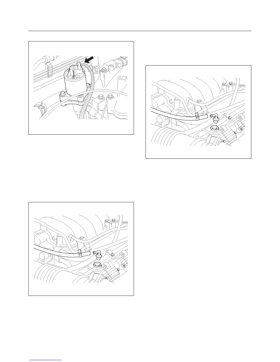
Positive Crankcase Ventilation
(PCV) Valve
Removal Procedure
1. Remove the vacuum hose at the PCV valve.
f
Slide the clamp back to release the hose.
2. Pull the PCV valve from the rubber grommet in the
right valve cover.
014RW097
Inspection Procedure
1. Shake the valve and listen for the rattle of the needle
inside the valve.
2. If the valve does not rattle, replace the valve.
Installation Procedure
1. Push the PCV valve into the rubber grommet in the
left valve cover.
2. Install the vacuum hose on the PCV valve and secure
the vacuum hose with the clamp.
014RW097
Wiring and Connectors
Wiring Harness Service
The control module harness electrically connects the
control module to the various solenoids, switches and
sensors in the vehicle engine compartment and
passenger compartment.
Replace wire harnesses with the proper part number
replacement.
Because of the low amperage and voltage levels utilized
in powertrain control systems, it is essential that all wiring
in environmentally exposed areas be repaired with crimp
and seal splice sleeves.
The following wire harness repair information is intended
as a general guideline only. Refer to
Chassis Electrical for
all wire harness repair procedures.
Connectors and Terminals
Use care when probing a connector and when replacing
terminals. It is possible to short between opposite
terminals. Damage to components could result. Always
use jumper wires between connectors for circuit
checking. NEVER probe through Weather-Pack seals.
Use an appropriate connector test adapter kit which
contains an assortment of flexible connectors used to
probe terminals during diagnosis. Use an appropriate
fuse remover and test tool for removing a fuse and to
adapt the fuse holder to a meter for diagnosis.
Open circuits are often difficult to locate by sight because
oxidation or terminal misalignment are hidden by the
connectors. Merely wiggling a connector on a sensor, or
in the wiring harness, may temporarily correct the open
circuit. Intermittent problems may also be caused by
oxidized or loose connections.
6E2–486
RODEO 6VD1 3.2L ENGINE DRIVEABILITY AND EMISSIONS
Be certain of the type of connector/terminal before
making any connector or terminal repair. Weather-Pack
and Com-Pack III terminals look similar, but are serviced
differently.
PCM Connectors and Terminals
Removal Procedure
1. Remove the connector terminal retainer.
2. Push the wire connected to the affected terminal
through the connector face so that the terminal is
exposed.
3. Service the terminal as necessary.
Installation Procedure
1. Bend the tab on the connector to allow the terminal to
be pulled into position within the connector.
2. Pull carefully on the wire to install the connector
terminal retainer.
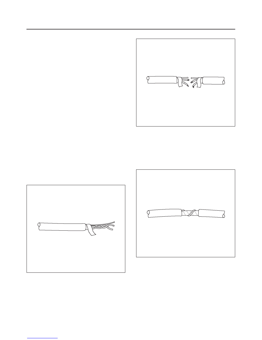
Wire Harness Repair: Twisted
Shielded Cable
Removal Procedure
1. Remove the outer jacket.
2. Unwrap the aluminum/mylar tape. Do not remove the
mylar.
047
3. Untwist the conductors.
4. Strip the insulation as necessary.
048
Installation Procedure
1. Splice the wires using splice clips and rosin core
solder.
2. Wrap each splice to insulate.
3. Wrap the splice with mylar and with the drain
(uninsulated) wire.
049
Нет комментариевНе стесняйтесь поделиться с нами вашим ценным мнением.
Текст