Isuzu Rodeo UE. Manual — part 488
TRANSMISSION CONTROL SYSTEM (4L30–E)
7A1–71
DTC P0758 Shift Solenoid B Electrical
D07RW014
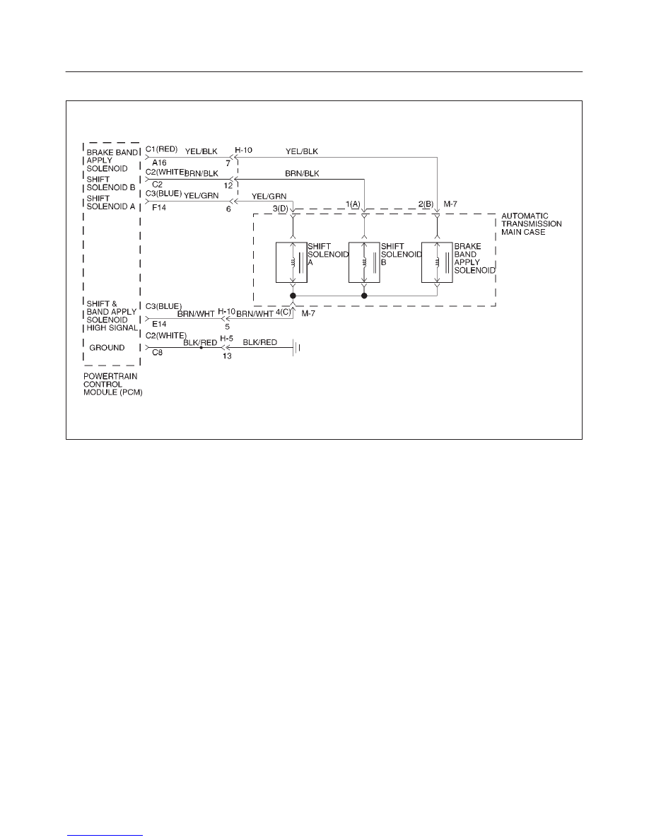
Circuit Description
f
The shift solenoid B is a simple on/off solenoid
located in the main case valve body. It is normally
open. When the port is open, fluid pressure actuates
the shift valve. In first or second gear, the Powertrain
Control Module (PCM) energizes the solenoid to
close a fluid inlet port.
f
The solenoid is activated by current. This current is
produced by applying a voltage to one side (the High
side) and a ground to the other side (Low side).
f
The High Side Driver (HSD) is a circuit of the PCM
that acts as a switch between the solenoids and the
supply voltage. The High side of the solenoid is
permanently supplied with voltage. In BACKUP
MODE or when the ignition is off, the HSD is turned
off.
This DTC detects a continuous open or short to ground in
the shift solenoid B circuit or shift solenoid B. This is a
type “B” DTC.
Conditions For Setting The DTC
f
Ignition is “on”, Engine “run”.
f
Battery voltage is between 10 and 16 volts.
f
The PCM commands the solenoid “on” and the
voltage remains high (B+), or the PCM commands
the solenoid “off” and the voltage remains low (zero
volts).
f
All conditions met for 0.33 seconds.
Action Taken When The DTC Sets
f
Fixed to 4th gear.
f
Maximum line pressure.
f
Inhibit TCC engagement.
f
The PCM will illuminate the Malfunction Indicator
Lamp (MIL) and CHECK TRANS Lamp.
Conditions For Clearing The MIL/DTC
f
The PCM will turn off the MIL and CHECK TRANS
Lamp after three consecutive ignition cycles without a
failure reported.
f
The DTC can be cleared from the PCM history by
using a scan tool.
f
The DTC will be cleared from history when the vehicle
has achieved 40 warmup cycles without a failure
reported.
f
The PCM will cancel the DTC default actions when
the fault no longer exists and the ignition is cycled “off”
long enough to power down the PCM.
Diagnostic Aids
f
Inspect the wiring for poor electrical connections at
the PCM and at the transmission 16–way connector.
Look for possible bent, backed out, deformed or
damaged terminals. Check for weak terminal tension
as well. Also check for a chafed wire that could short
to bare metal or other wiring. Inspect for a broken wire
inside the insulation.

7A1–72 TRANSMISSION CONTROL SYSTEM (4L30–E)
f
When diagnosing for a possible intermittent short or
open condition, move the wiring harness while
observing test equipment for a change.
Test Description
The numbers below refer to the step numbers on the
diagnostic chart:
5. This test measures the resistance of the component.
7. This test checks the function of the shift solenoid B
and the transmission internal wiring harness.
11.This test checks for power to the shift solenoid B
from the ignition through the PCM.
Shift Solenoid Status Chart
Gear
Shift solenoid A
Shift solenoid B
1st
OFF
ON
2nd
ON
ON
3rd
ON
OFF
4th
OFF
OFF
DTC P0758 Shift Solenoid B Electrical
Step
Action
Yes
No
1
Were you sent here from the “Powertrain On–Board Diagnostic
(OBD) System Check”?
Go to Step 2
Go to OBD
System Check
Refer to
Driveability and
Emission in
Engine section
2
1. Install the scan tool.
2. With the engine “on”, turn the ignition switch “on”.
NOTE: Before clearing DTC(s), use the scan tool to record “Freeze
Frame” and “Failure Records” for reference, as data will be lost
when the “Clear Info” function is used.
3. Record the DTC “Freeze Frame” and “Failure Records”.
Were DTCs P0753, P0758, P1860 set?
Go to Step 4
Go to Step 3
3
1. The engine “on”.
2. Apply brake pedal and select transmission range “D”.
3. Press and hold down the winter switch and select transmission
mode “winter”.
Does the scan tool display DTC P0758 at 3rd gear?
Go to Step 8
Go to Diagnostic
Aids
4
1. Turn the ignition “off”.
2. Disconnect the C2 (WHITE) and C3 (BLUE) PCM connectors.
3. Turn the ignition “on”.
4. Using the J39200 DVOM, measure the voltage between PCM
connector terminals C2–C2 and C2–C8.
Is the voltage within 10 – 12 volts?
Go to Step 15
Go to Step 5
5
1. Turn the ignition “off”.
2. Using the J39200 DVOM, measure the resistance between
PCM connector terminals C2–C2 and C3–E14.
Is the resistance within 18 – 20 ohms?
Go to Step 16
Go to Step 6
6
1. Disconnect the transmission 16–way connector H–10.
2. Using the J39200 DVOM, measure the resistance between
terminals H10–12 and H10–5.
Is the resistance within 18 – 20 ohms?
Go to Step 17
Go to Step 7
7
1. Disconnect the transmission main case connector M–7.
2. Using the J39200 DVOM, measure the resistance between
terminals M7–1(A) and M7–4(C).
Is the resistance within 18 – 20 ohms?
Go to Step 18
Go to Step 19

TRANSMISSION CONTROL SYSTEM (4L30–E)
7A1–73
DTC P0758 Shift Solenoid B Electrical (Cont’d)
Step
No
Yes
Action
8
1. Turn the ignition “off”.
2. Disconnect the C2 (WHITE) and C3 (BLUE) PCM connectors.
3. Using the J39200 DVOM, measure the resistance between
PCM connector terminals C2–C2 and C3–E14.
Is the resistance within 18 – 20 ohms?
Go to Step 9
Go to Step 10
9
Using the J39200 DVOM, check a continuity between PCM
connector terminal C2–C2 and ground.
Is there a continuity?
Go to Step 20
Go to Step 11
10
1. Disconnect the transmission 16–way connector H–10.
2. Using the J39200 DVOM, measure the resistance between
terminals H10–12 and H10–5.
Is the resistance within 18–20 ohms?
Go to Step 21
Go to Step 12
11
Using the J39200 DVOM, check a continuity between PCM
connector terminal C3–E14 and ground.
Is there a continuity?
Go to Step 22
Go to Step 13
12
1. Disconnect the transmission main case connector M–7.
2. Using the J39200 DVOM, measure the resistance between
terminals M7–1(A) and M7–4(C).
Is the resistance within 18 – 20 ohms?
Go to Step 23
Go to Step 24
13
Check every connection of the PCM and transmission 16–way
connector H–10.
Was a problem found and corrected?
Go to Step 26
Go to Step 14
14
1. Connect the C2 (WHITE) and C3 (BLUE) PCM connectors to
the PCM.
2. Turn the ignition “on”, the engine “on”.
3. Repeat Step 3.
Does the scan tool display DTC P0758 at 3rd gear?
Go to Step 25
Go to Diagnostic
Aids
15
The wiring harness between PCM connector terminal
C2–C2 and transmission main case terminal M7–1(A) is shorted
to voltage.
Was a problem found and corrected?
Go to Step 26
—
16
The PCM internal terminal C2–C2 is shorted to voltage.
Replace the PCM. Refer to Powertrain Control Module (PCM) in
Automatic Transmission (4L30–E) section.
Is the replacement complete?
Go to Step 26
—
17
The wiring harness between PCM connector and transmission
16–way connector is shorted.
Was a problem found and corrected?
Go to Step 26
—
18
The wiring harness between transmission 16–way connector and
transmission main case connector is shorted.
Was a problem found and corrected?
Go to Step 26
—
19
The shift solenoid B is faulty, or the internal wiring harness from
the shift solenoid B is shorted.
Was a problem found and corrected?
Go to Step 26
—
20
The wiring harness between PCM connector terminal
C2–C2 and transmission main case connector terminal M7–1(A)
is shorted to ground.
Was a problem found and corrected?
Go to Step 26
—

7A1–74 TRANSMISSION CONTROL SYSTEM (4L30–E)
DTC P0758 Shift Solenoid B Electrical (Cont’d)
Step
No
Yes
Action
21
The wiring harness between PCM connector terminal C2–C2 and
transmission 16–way connector terminal H10–12, or between
PCM connector terminal C3–E14 and 16–way connector terminal
H10–5 is open.
Was a problem found and corrected?
Go to Step 26
—
22
The wiring harness between PCM connector terminal C3–E14
and transmission main case connector terminal M7–4(C) is
shorted to ground.
Was a problem found and corrected?
Go to Step 26
—
23
The wiring harness between transmission 16–way connector
terminal H10–12 and transmission main case connector terminal
M7–1(A), or between H10–5 and M7–4(C) is open.
Was a problem found and corrected?
Go to Step 26
—
24
The internal wiring harness from the shift solenoid B is open, or
the shift solenoid B is faulty.
Was a problem found and corrected?
Go to Step 26
—
25
Replace the PCM.
Is the replacement complete?
Go to Step 26
—
26
1. After the repair is complete, use the scan tool to select “DTC”,
then “Clear Info” function and operate the vehicle under the
following conditions:
f
The shift solenoid B is commanded “on” and voltage drops to
zero.
f
The shift solenoid B is commanded “off” and voltage
increases to B+.
2. Review the scan tool “DTC Info”.
Has the last test failed or is the current DTC displayed?
Begin diagnosis
again
Go to Step 1
Repair verified
Exit DTC table
Нет комментариевНе стесняйтесь поделиться с нами вашим ценным мнением.
Текст