Isuzu Rodeo UE. Manual — part 230

6E1–291
RODEO X22SE 2.2L ENGINE DRIVEABILITY AND EMISSION
DTC P0532 A/C Refigerant Pressure Sensor Circuit Low Input
Step
Action
Value(s)
Yes
No
1
Was the ”On–Board Diagnostic (OBD) System Check”
performed?
—
Go to Step 2
Go to OBD
System
Check
2
1. Ignition ON, Engine OFF.
2. Review and record Scan Tool’s Failure Records
data, then clear the DTC’s.
3. Operate the vehicle within the Failure Records
conditions as noted.
4. Using the Tech 2, monitor ”DTC” info for DTC
P0532.
Does the Tech 2 indicate DTC P0532 ”Ran and
Passed?”
—
Refer to
Diagnostic
Aids
Go to Step 3
3
1. Ignition OFF.
2. Disconnect the A/C refrigerant pressure sensor
wiring harness connector from the A/C refrigerant
pressure sensor.
3. Start the vehicle, and monitor the A/C refrigerant
pressure value with the Tech 2.
Does the A/C refrigerant pressure sensor value on the
Tech 2 hold steadily at the given value?
less than 0.1
volts
Go to Step 5
Go to Step 4
4
Check the A/C refrigerant pressure sensor signal
circuit, between the A/C refrigerant pressure sensor
and the Powertrain Control Module (PCM), for a short
to voltage.
Was the problem found?
—
Verify repair
Go to Step 12
5
Check the A/C refrigerant pressure sensor signal
circuit, between the A/C refrigerant pressure sensor
and the PCM for the following conditions:
f
A short to ground
f
An open circuit
Was the problem found?
—
Verify repair
Go to Step 6
6
Check the 5 volt signal circuit, between the A/C
refrigerant pressure sensor and the PCM, for the
following conditions:
f
An open circuit
f
A short to voltage
f
A short to ground
Was the problem found?
—
Verify repair
Go to Step 7
7
1. Ignition OFF.
2. Place a Digital Voltmeter (DVM), set to measure
voltage between the 5 volt signal circuit and ground.
3. Ignition ON, Engine OFF.
Does the DVM indicate the following value?
about 5 volts
Go to Step 8
Go to Step 12

6E1–292
RODEO X22SE 2.2L ENGINE DRIVEABILITY AND EMISSION
DTC P0532 A/C Refigerant Pressure Sensor Circuit Low Input
(Cont'd)
Step
No
Yes
Value(s)
Action
8
1. Ignition OFF.
2. Place a fused jumper between the A/C refrigerant
pressure sensor and the 5 volt signal circuit, both at
the wiring harnesses A/C refrigerant pressure
sensor connector.
3. Ignition ON, Engine OFF.
4. Observe the A/C refrigerant pressure sensor value
displayed on the Tech 2.
Does the Tech 2 read the following value?
about 5 volts
Go to Step 9
Go to Step 12
9
Check the A/C refrigerant pressure sensor and the
PCM, for the following conditions:
f
An open circuit
f
A short to ground
f
A short to voltage
Was the problem found?
—
Verify repair
Go to Step 10
10
1. Ignition OFF.
2. Place a Digital Voltmeter (DVM), set to measure
voltage between the ground circuit and the 5 volt
signal circuit, both at the wiring harnesses A/C
refigerant pressure sensor connector.
3. Ignition ON, Engine OFF.
Does the DVM indicate the following value?
about 5 volts
Go to Step 11
Go to Step 12
11
Replace the A/C refrigerant pressure sensor.
Verify Repair.
—
—
—
12
Replace the PCM.
IMPORTANT: The replacement PCM must be
programmed. Refer to On–Vehicle Service in
Powertrain Control Module and Sensors for
procedures.
And also refer to latest Service Bulletin.
Check to see if the Latest software is released or not.
And then Down Load the LATEST PROGRAMMED
SOFTWARE to the replacement PCM.
Verify repair.
—
—
—
6E1–293
RODEO X22SE 2.2L ENGINE DRIVEABILITY AND EMISSION
DIAGNOSTIC TROUBLE CODE (DTC) P0533 A/C REFRIGERANT PRESSURE
SENSOR CIRCUIT HIGH INPUT
D06RX060
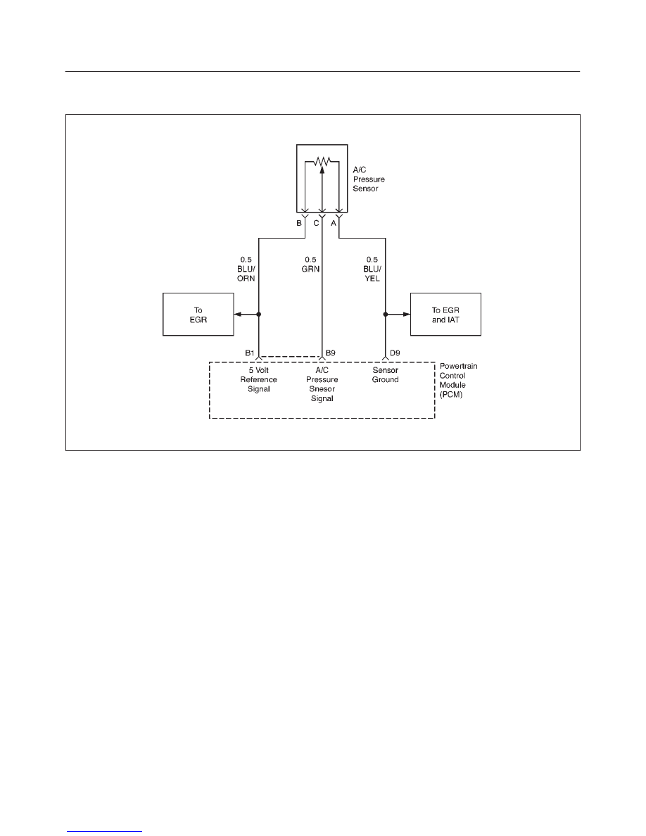
Circuit Description
The Powertrain Control Module (PCM) monitors the A/C
refigerant pressure through the use of a three wire
sensor. If the PCM senses the pressure falls below a
threshold value, then DTC P0533 will set. DTC P0533 is a
type D code.
Conditions for Setting the DTC
f
A/C pressure sensor is above 250 counts (4.88 volts)
for 125 seconds within a 250 seconds test sample.
Action Taken When the DTC Sets
f
The PCM will not illuminate the Malfunction Indicator
Lamp (MIL).
f
The PCM will store the conditions that were present
when the DTC was set as Freeze Frame and in Failure
Records.
Conditions for Clearing the DTC
f
A history DTC will clear after 40 consecutive trips
without a reported failure.
f
The DTC can be cleared using a Scan Tool’s ”Clear
Info” function.
Diagnostic Aids
f
Poor Conditions, or a damaged harness – Inspect the
harness connectors for: backed–out terminals,
improper mating or damaged terminals. Also, check
for open circuits, shorts to ground, and shorts to
voltage.

6E1–294
RODEO X22SE 2.2L ENGINE DRIVEABILITY AND EMISSION
DTC P0533 A/C Refigerant Pressure Sensor Circuit High Input
Step
Action
Value(s)
Yes
No
1
Was the ”On–Board Diagnostic (OBD) System Check”
performed?
—
Go to Step 2
Go to OBD
System
Check
2
1. Ignition ON, Engine OFF.
2. Review and record Scan Tool’s Failure Records
data, then clear the DTC’s.
3. Operate the vehicle within the Failure Records
conditions as noted.
4. Using the Tech 2, monitor ”DTC” info for DTC
P0533.
Does the Tech 2 indicate DTC P0533 ”Ran and
Passed?”
—
Refer to
Diagnostic
Aids
Go to Step 3
3
1. Ignition OFF.
2. Disconnect the A/C refrigerant pressure sensor
wiring harness connector from the A/C refrigerant
pressure sensor.
3. Start the vehicle, and monitor the A/C refrigerant
pressure value with the Tech 2.
Does the A/C refrigerant pressure sensor value on the
Tech 2 hold steadily at the given value?
less than 0.1
volts
Go to Step 5
Go to Step 4
4
Check the A/C refrigerant pressure sensor signal
circuit, between the A/C refrigerant pressure sensor
and the Powertrain Control Module (PCM), for a short
to voltage.
Was the problem found?
—
Verify repair
Go to Step 12
5
Check the A/C refrigerant pressure sensor signal
circuit, between the A/C refrigerant pressure sensor
and the PCM for the following conditions:
f
A short to ground
f
An open circuit
Was the problem found?
—
Verify repair
Go to Step 6
6
Check the 5 volt signal circuit, between the A/C
refrigerant pressure sensor and the PCM, for the
following conditions:
f
An open circuit
f
A short to voltage
f
A short to ground
Was the problem found?
—
Verify repair
Go to Step 7
7
1. Ignition OFF.
2. Place a Digital Voltmeter (DVM), set to measure
voltage between the 5 volt signal circuit and ground.
3. Ignition ON, Engine OFF.
Does the DVM indicate the following value?
about 5 volts
Go to Step 8
Go to Step 12
Нет комментариевНе стесняйтесь поделиться с нами вашим ценным мнением.
Текст