Isuzu Rodeo UE. Manual — part 459
7A–52
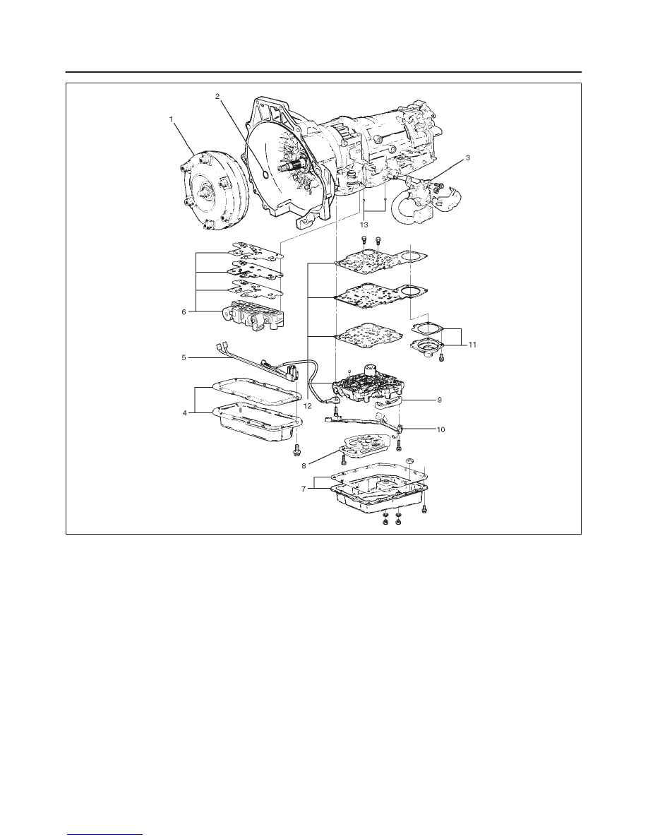
AUTOMATIC TRANSMISSION (4L30–E)
240RW022
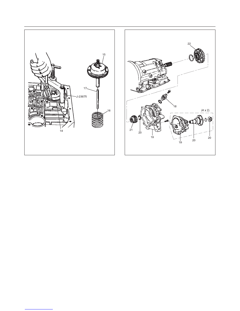
14. Turn transmission to vertical position to drain fluid.
Return back to horizontal position when drained.
f
Install J–23075 servo piston spring compressor
with offset to the rear of case.
f
Compress servo piston assembly.
f
Remove servo piston retaining ring (14).
f
Slowly release servo piston assembly (15).
f
Remove tool.
15. Remove servo piston assembly (15), return spring
(16), and servo apply rod (17).
7A–53
AUTOMATIC TRANSMISSION (4L30–E)
242RS002
16. Rotate transmission to horizontal position, pan side
down.
f
Remove one 10mm screw, and speed sensor (18)
with “O” ring.
17. Remove seven 8mm extension housing hexagon
socket head screws, extension housing assembly
(19), and gasket.
18. Remove retaining ring (20). (4
×
4)
NOTE: Use extra long, needle nose pliers.
f
Remove flange nut (20). (4
×
2)
f
Remove flange and O–ring (20). (4
×
2)
19. Remove speed wheel (21).
20. Remove wheel parking lock (with seal ring) (22).
241RW012
21. Rotate transmission to vertical position, converter
housing up.
f
Loosen the converter housing and oil pump
assembly fixing screws, but do not remove, the five
13 mm inner screws unless oil pump disassembly is
required.
f
Remove seven outer screws.
f
Remove converter housing and oil pump assembly
(23).
22. Remove gasket (24).
23. Remove selective thrust washer (25).

7A–54
AUTOMATIC TRANSMISSION (4L30–E)
241RW004
24. Remove fourth clutch retainer (26).
25. Grasp turbine shaft and lift out the overrun clutch
housing assembly (27) and fourth clutch plates (28).
26. Remove thrust bearing assembly (29).
27. Remove overdrive internal gear (30).
28. Remove thrust washer (31).
252RS001
29. Remove adapter case and center support assembly
(with fourth clutch piston) (32).
30. Remove seal ring (33).
31. Remove selective thrust washer (34) and two O-ring
seals (35) from main case.
32. Use J–23327 and J–23327–90 compressor to
compress the fourth clutch spring retainer and
springs (37).
f
Release snap ring (36) from groove.
f
Remove clutch compressor and snap ring (36).
33. Remove retainer and spring assembly (37).
34. Insert two converter housing/main case screws to
hold adapter case while pulling out fourth clutch
piston (38).
f
Remove fourth clutch piston assembly (38) from the
adapter case.
f
Remove converter housing/main case screws.
35. Grasp intermediate shaft, twist and pull out the
second and third clutch drum assemblies with reverse
clutch plates while holding onto output shaft (39).
7A–55
AUTOMATIC TRANSMISSION (4L30–E)
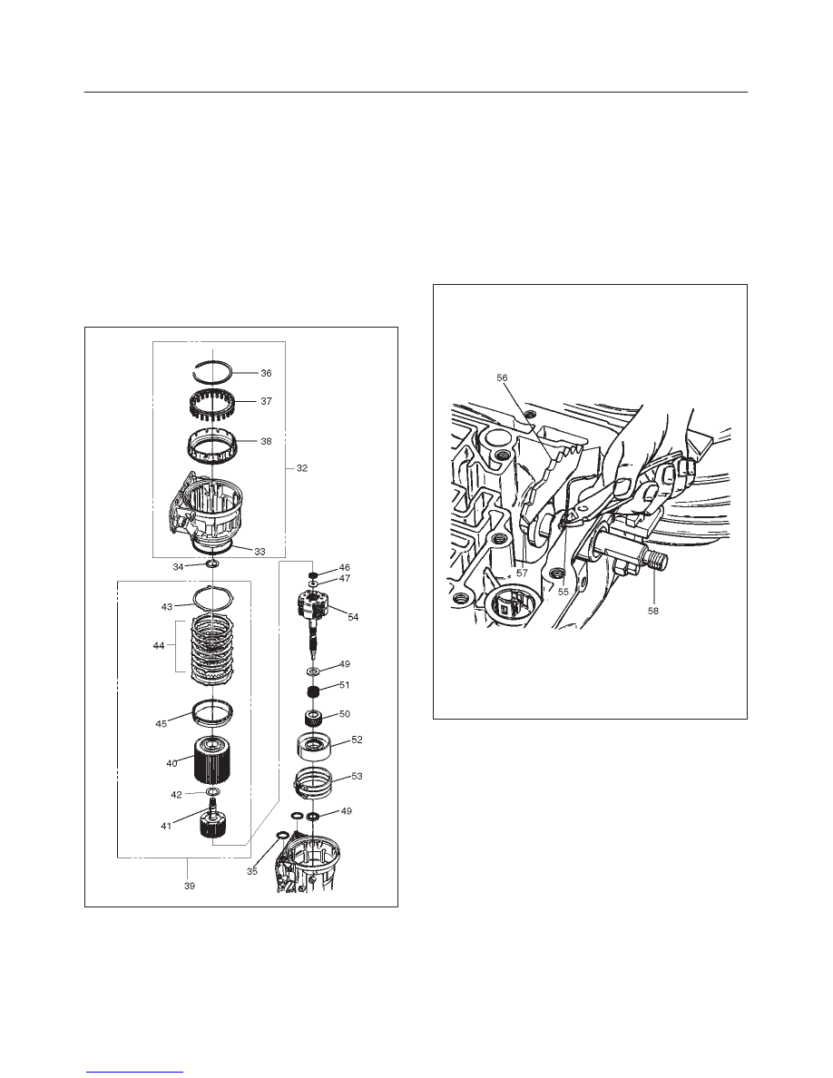
36. Separate second (40) and third clutch (41)
assemblies.
37. Remove thrust washer (42).
38. Remove reverse clutch plates (43 and 44) and
reverse clutch pressure plate (45).
39. Remove bearing (46) and washer (47).
40. Remove planetary carrier assembly (48).
41. Remove thrust bearing (49).
42. Remove reaction sun gear (50)
43. Remove needle bearing (51).
44. Remove brake drum (52).
45. Remove brake band (53).
46. Remove thrust bearing (54).
242RW005
47. Rotate case to horizontal position, valve body side
facing up.
f
Remove spring pin (55), using cutting pliers, then
remove parking lock and selector lever assembly
(56).
NOTE: Insert wire in the center of the spring pin to
prevent it from collapsing during removal. Be aware of pin
height. Protect machined face of main case.
48. Remove parking lock and range selector lever 17 mm
nut (57).
49. Remove parking lock and range selector lever (56),
and actuator assembly.
50. Remove selector shaft (58).
NOTE: Inspect the shaft for burrs before removing to
prevent damaging seal. If necessary, remove burrs by
lightly sanding with an oilstone.
249RS004
Reassembly
1. Inspect selector shaft seal and replace it if necessary.
NOTE: Use a seal installer when replacing the seal.
f
Install selector shaft.
NOTE: Spring pin groove must be positioned inside the
case.
2. Install spring pin. Be sure the selector shaft can move
freely. Do not push the pin flush with the case surface.
Leave enough height for removal.
3. Install actuator assembly (1).
4. Install parking lock and range selector lever (2) and
new 17 mm nut. Tighten the nut to the specified
torque.
Torque: 22 N
•
m (16 lb ft)
Нет комментариевНе стесняйтесь поделиться с нами вашим ценным мнением.
Текст