Isuzu Rodeo UE. Manual — part 460
7A–56
AUTOMATIC TRANSMISSION (4L30–E)
249RS005
5. Rotate main case to vertical position, extension end
facing down.
f
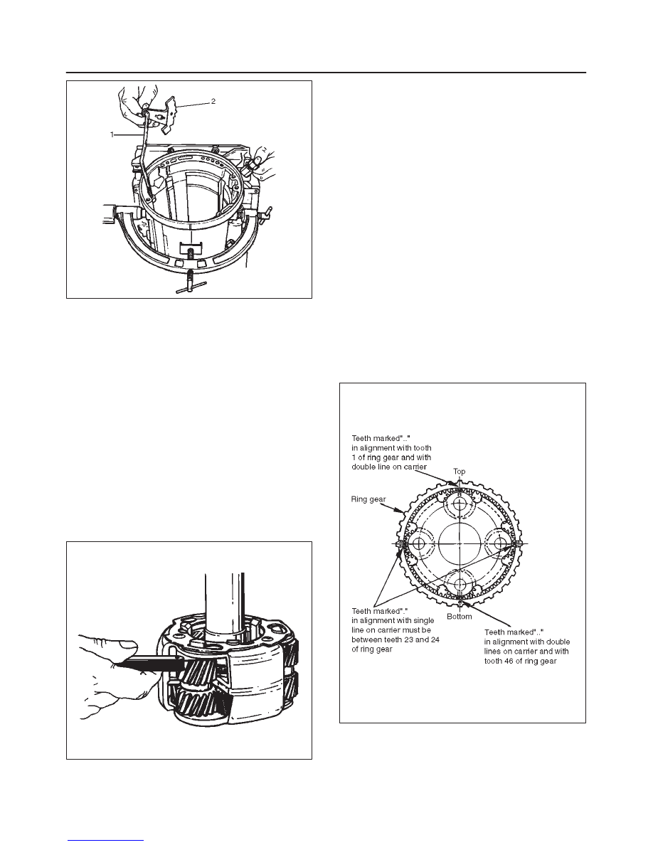
Install brake band assembly (3).
NOTE: Be sure to align servo pin area with the servo hole.
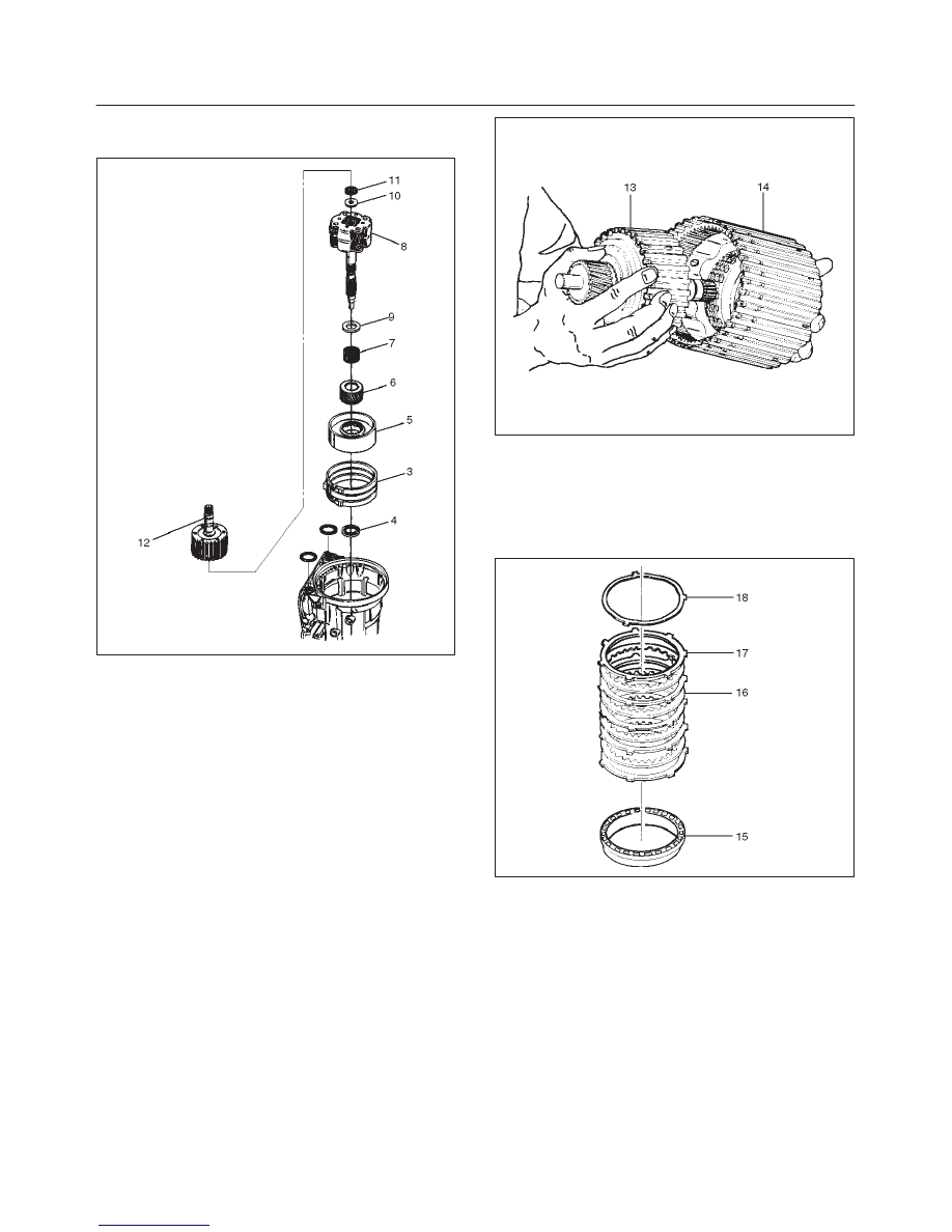
6. Install thrust bearing (4).
NOTE: The case bushing acts as a guide for the thrust
bearing.
7. Install brake drum (5).
8. Install reaction sun gear (6).
9. Install needle bearing (7).
10. Inspect planetary carrier assembly (8) for wear and
damage. If necessary replace it.
f
Measure pinion end play clearance with a feeler
gauge.
Clearance: 0.13mm–0.89mm (0.005 in–0.035 in)
If clearance is outside specified value, replace the
planetary carrier assembly.
248RS001
11. Install the thrust bearing (9) on the output shaft.
NOTE: Use petroleum jelly to hold the thrust bearing in
place.
12. Align planetary pinions. Each pinion is marked with
double points to indicate the master tooth space and
exactly opposite with a single point to indicate the
master tooth. The markings on the planetary carrier
consist of double lines which are to be lined up with
the double points on two opposite pinions; the single
lines are to be lined up with the single points on the
other two pinions.
f
After all four pinions are lined up, slide on the third
clutch assembly. Rotate third clutch and check
mark alignment. Considering that the ring gear
tooth between the double points of one planetary
pinion is tooth number 1, count the teeth to check
that the single points on the two adjacent pinions
are between teeth 23 and 24 of the ring gear, and
that the ring gear tooth between the double points of
the opposite pinion is tooth number 46. If the ring
gear and pinions are not lined up, remove and
realign them.
13. Install planetary carrier (8) with third clutch (12).
NOTE: Do not force. When properly aligned, the parts will
fit together easily.
248RS002
14. Remove the third clutch (12).
15. Install bearing (11) and washer (10).
7A–57
AUTOMATIC TRANSMISSION (4L30–E)
NOTE: Use petroleum jelly to hold the washer and
bearing in place.
242RW002
16. Carefully align the second clutch plate inner tangs.
f
Install thrust washer, tangs pointing downward, and
locating tang positioned in slot on second clutch
hub.
NOTE: Use petroleum jelly to hold thrust washer in place.
17. Install third clutch and intermediate shaft assembly
(13) into the second clutch drum (14).
18. Install second and third clutch assemblies into the
main case. Twist output shaft and clutch assemblies
to ensure proper fit.
247RS001
19. Install pressure plate (15) with lip side up, tang facing
valve body face.
20. Install reverse clutch plates. Start with a steel plate
(17) and alternate with a lined plate (16).
21. Install waved clutch plate (18) with center tang facing
valve body side.
247RS002
22. Second clutch end play measurement
1. Install the J–23085–A Selective washer gauging
tool (with spacer ring) on the case flange and
against the intermediate shaft.
2. Position the inner shaft of the gauging tool against
the thrust surface of the second clutch hub.
3. Tighten thumb screw. Remove the tool.
4. Fit the spacer ring on the inner shaft of the tool.

7A–58
AUTOMATIC TRANSMISSION (4L30–E)
5. Measure the gap and select appropriate washer
as shown in the chart.
Selective Thrust Washer
Gap: mm(in)
Color
1.53 – 1.63 (0.060 – 0.064)
Yellow
1.72 – 1.82 (0.068 – 0.072)
Red
1.91 – 2.01 (0.075 – 0.079)
Black
2.10 – 2.20 (0.083 – 0.087)
Natural
2.29 – 2.39 (0.090 – 0.094)
Green
2.48 – 2.58 (0.098 – 0.102)
Blue
FOLLOWING THE PROCEDURE SHOULD
RESULT IN FINAL END–PLAY FROM 0.36 mm TO
0.79 mm (0.014 in TO 0.031 in)
247RS003
247RS004
23. Inspect fourth clutch piston seals and replace if
necessary.
f
Lubricate J–38554 fourth clutch piston fitter and
install it on fourth clutch piston (19).
f
Install fourth clutch piston (19) in adapter case (20).
f
Remove fitter.
252RS003
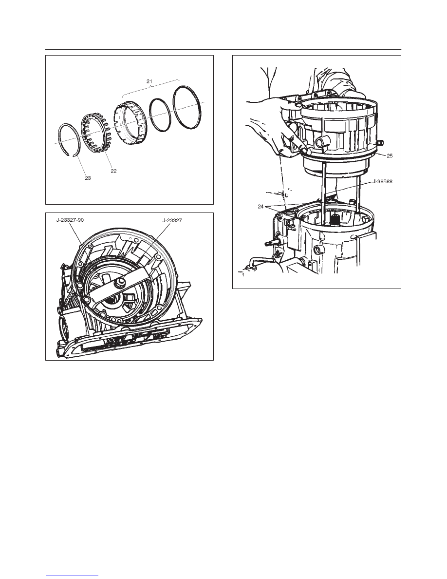
24. Install retainer and spring assembly (22) into fourth
clutch piston (21).
25. Install snap ring (23) in adapter case.
f
Install J–23327 and J–23327–90 fourth clutch
spring compressor.
f
Seat snap ring in groove.
f
Remove compressor.
7A–59
AUTOMATIC TRANSMISSION (4L30–E)
252RW002
252RS004
26. Install selective washer using petroleum jelly.
27. Install two O-ring seals (24) in main case and adapter
case/main case seal ring (25).
28. Install J–38588 guide pins.
f
Install adapter case and center support assembly to
main case.
242RS004
29. Install thrust washer (26) into adapter case, with
tangs pointing downwards.
30. Preassemble overdrive internal gear (27) and thrust
bearing assembly (28) onto the turbine shaft and
overrun clutch assembly.
NOTE: Install bearing assembly, black side up. Use
petroleum jelly to keep assembly in place.
31. Install overdrive carrier (30) and internal gear
assembly into adapter case.
32. Install fourth clutch plates (29) in the following order:
Steel, Lined, Steel, Steel, Lined, Steel. Steel plates
go in with short tang facing towards valve body
surface.
33. Install fourth clutch retainer(31) with the notch facing
up and positioned towards valve body surface.
Нет комментариевНе стесняйтесь поделиться с нами вашим ценным мнением.
Текст