Isuzu Rodeo UE. Manual — part 252

6E1–379
RODEO X22SE 2.2L ENGINE DRIVEABILITY AND EMISSION
Hesitation, Sag, Stumble
1. OBD system check.
2. TP.
3. MAP output check.
4. Fuel system diagnosis.
5. Fuel injector and fuel injector
balance test.
6. EVAP emission canister purge
valve.
7. Ignition system.
EGR Operation
EGR System Check
Generator Output Voltage (refer
to Chassis Electrical)
Calibration ID/Service Bulletins
Ignition System Check
Cuts Out, Misses
1. OBD system check.
2. Cylinder balance test.
Ignition System Check
Rough, Unstable, or Incorrect Idle,
Stalling
1. OBD system check.
2. Fuel injector and fuel injector
balance test.
3. EVAP emission canister purge
valve check.
4. Ignition system.
5. IAC operation.
6. EGR operation.
MAP Output Check
Throttle Linkage
IAC System Check
EGR System Check
A/C Clutch Control Circuit Diag-
nosis
Crankcase Ventilation System
Calibration ID/Service Bulletins
Generator Output Voltage (refer
to Chassis Electrical)
Exhaust Diagnosis
Poor Fuel Economy
1. OBD system check.
2. Careful visual/physical inspection.
3. Ignition system.
4. Cooling system.
TCC Operation
Exhaust System (refer to Engine
Exhaust)
Engine Cranks But Will Not Run
1. OBD system check.
Fuel System Electrical
Diagnosis
Fuel System Diagnosis
Fuel Injector
Fuel Injector Balance Test
Excessive Exhaust Emissions or
Odors
1. OBD system check.
2. Emission test.
3. Cooling system.
4. Fuel system diagnosis.
5. Fuel injector and fuel injector
balance test.
6. EVAP emission canister purge
valve.
7. Crankcase ventilation system.
8. Ignition system.
9. MAP output check.
EGR System Check
Exhaust Diagnosis
Calibration ID/Service Bulletins
Dieseling, Run–On
1. OBD system check.
2. Careful visual/physical inspection.
3. Fuel system diagnosis.
—
Backfire
1. OBD system check.
2. Ignition system.
3. Fuel system diagnosis.
4. Fuel injector and fuel injector
balance test.
5. EGR operation, EGR system
check.
Exhaust System Diagnosis,
Intake Casting Flash, Ignition
System Check

6E1–380
RODEO X22SE 2.2L ENGINE DRIVEABILITY AND EMISSION
Misfire
1. OBD system check.
2. Ignition system.
3. Fuel system diagnosis.
4. Fuel injector and fuel injector
balance test.
Vibrations, Transmission,
Driveshaft and Axle
Catalyst Monitor
1. OBD system check.
2. Careful visual/physical inspection.
3. Heated oxygen sensors.
Exhaust System
Fuel Trim
1. OBD system check.
2. Careful visual/physical inspection.
3. Fuel system diagnosis.
4. Heated oxygen sensors.
Exhaust System Intake Air
System
Evaporative Emissions
1. OBD system check.
2. Careful visual/physical inspection.
3. Fuel system diagnosis.
—
Heated Oxygen Sensors
1. OBD system check.
2. Careful visual/physical inspection.
Exhaust System
6E1–381
RODEO X22SE 2.2L ENGINE DRIVEABILITY AND EMISSION
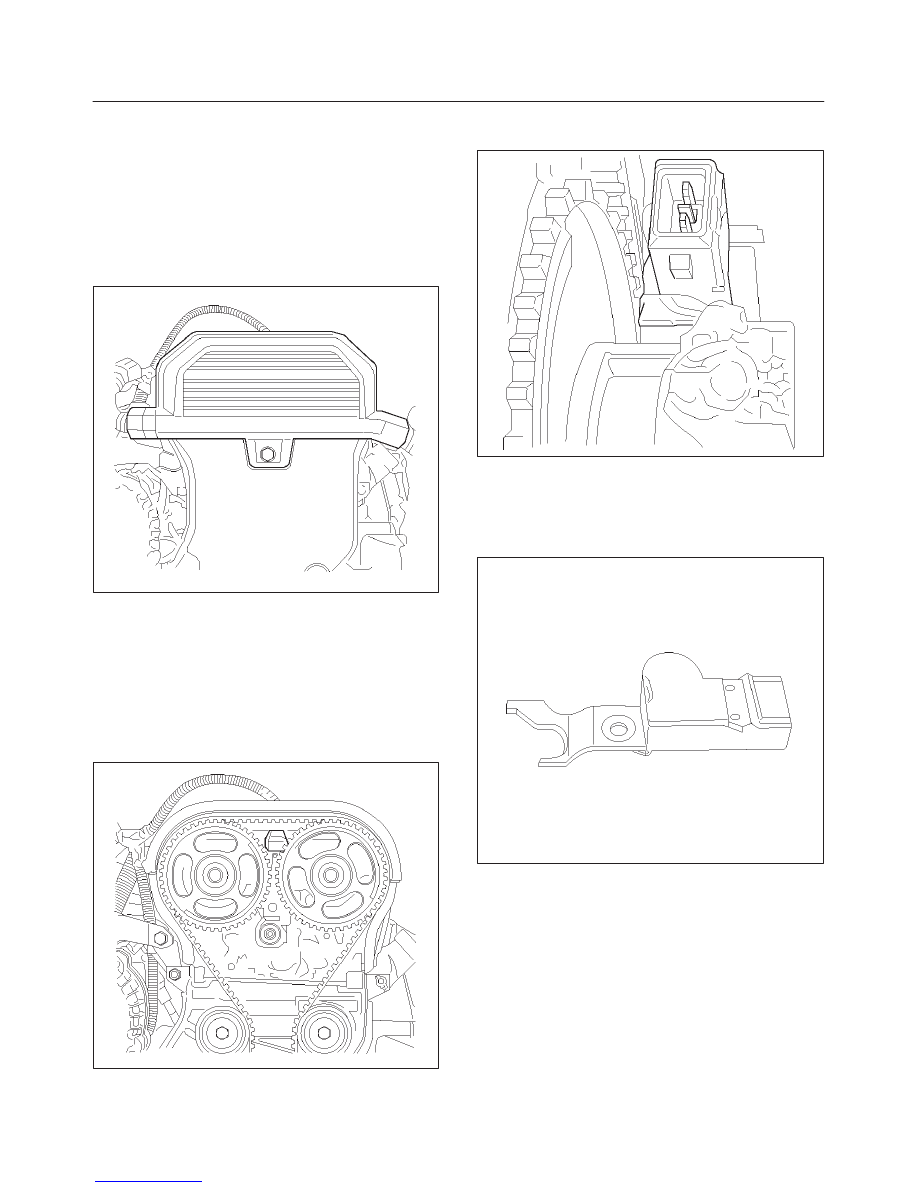
Camshaft Position (CMP)
Sensor
Removal Procedure
1. Disconnect the negative battery cable.
2. Remove spark plug cover on top of valve cover by
removing four retaining bolts.
3. Disconnect electrical connector from the sensor.
014RX003
4. Remove drive belt. Refer to Engine Mechanical
Section.
5. Remove top harness cover installed on timing belt
cover by removing a retaining screw.
6. Remove the retaining bolts holding crankshaft pulley,
and pull crankshaft pulley while wiggling. Refer to
Engine Mechanical Section.
7. Remove the retaining screws for timing belt cover and
timing belt cover.
014RX004
8. Remove the retaining bolt for the sensor and pull up
camshaft position sensor.
014RX005
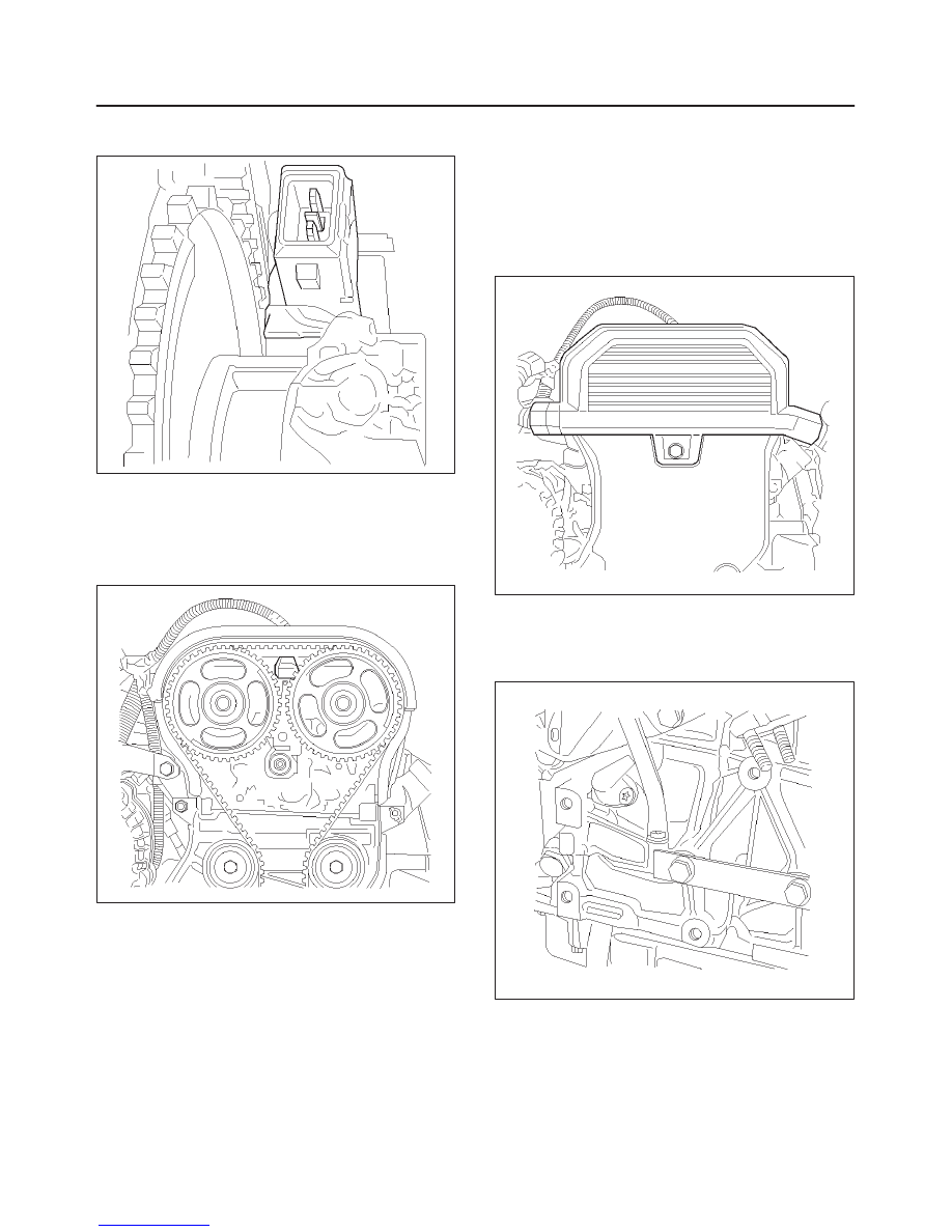
Installation Procedure
1. Insert camshaft position sensor in position.
2. Install retaining bolt.
014RX007
3. Install the timing belt cover and the retaining screws.
4. Install the crank shaft pulley and the mounting bolts.
Holes for mounting bolts are off the pitch. The pulley
can be mounted only one way to install all mounting
bolts. Tighten the bolts. Refer to Engine Mechanical
section.
6E1–382
RODEO X22SE 2.2L ENGINE DRIVEABILITY AND EMISSION
5. Install the drive belt. Refer to Engine Mechanical
Section.
014RX005
6. Install the top harness cover onto timing belt cover.
7. Connect electrical connector to the sensor and
securely lock it.
8. Install the spark plug cover.
9. Connect the negative battery cable.
014RX004
Crankshaft Position (CKP)
Sensor
Removal Procedure
1. Disconnect the negative battery cable.
2. Remove the drive belt. Refer to Engine Mechanical
Section.
014RX003
3. Remove the pwer steering pump and
mounting–bracket from engine. Refer to Engine
Mechanical Section.
4. Disconnect electrical connector from the sensor.
014RX006
Нет комментариевНе стесняйтесь поделиться с нами вашим ценным мнением.
Текст