Isuzu Rodeo UE. Manual — part 253
6E1–383
RODEO X22SE 2.2L ENGINE DRIVEABILITY AND EMISSION
5. Remove the retaining bolt and sensor from the engine
block.
NOTE: Use caution to avoid any hot oil that might drip
out.
0013
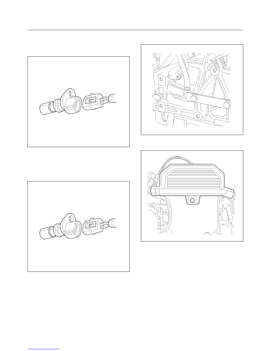
Installation Procedure
1. Install the crank shaft position sensor to its position.
2. Install and tighten the mounting bolt. Refer to Engine
Mechanical Section.
0013
3. Reinstall the power steering pump and bracket to the
engine.
014RX006
4. Reinstall the accessory drive belt.
5. Connect the negative battery cable.
014RX003
IMPORTANT:
PCM must re–learn Crankshaft Position
when the CKP sensor is replaced. Refer to CKP sensor
learn mode on the Tech 2, or Tooth Error Correction in the
Service Manual.
6E1–384
RODEO X22SE 2.2L ENGINE DRIVEABILITY AND EMISSION
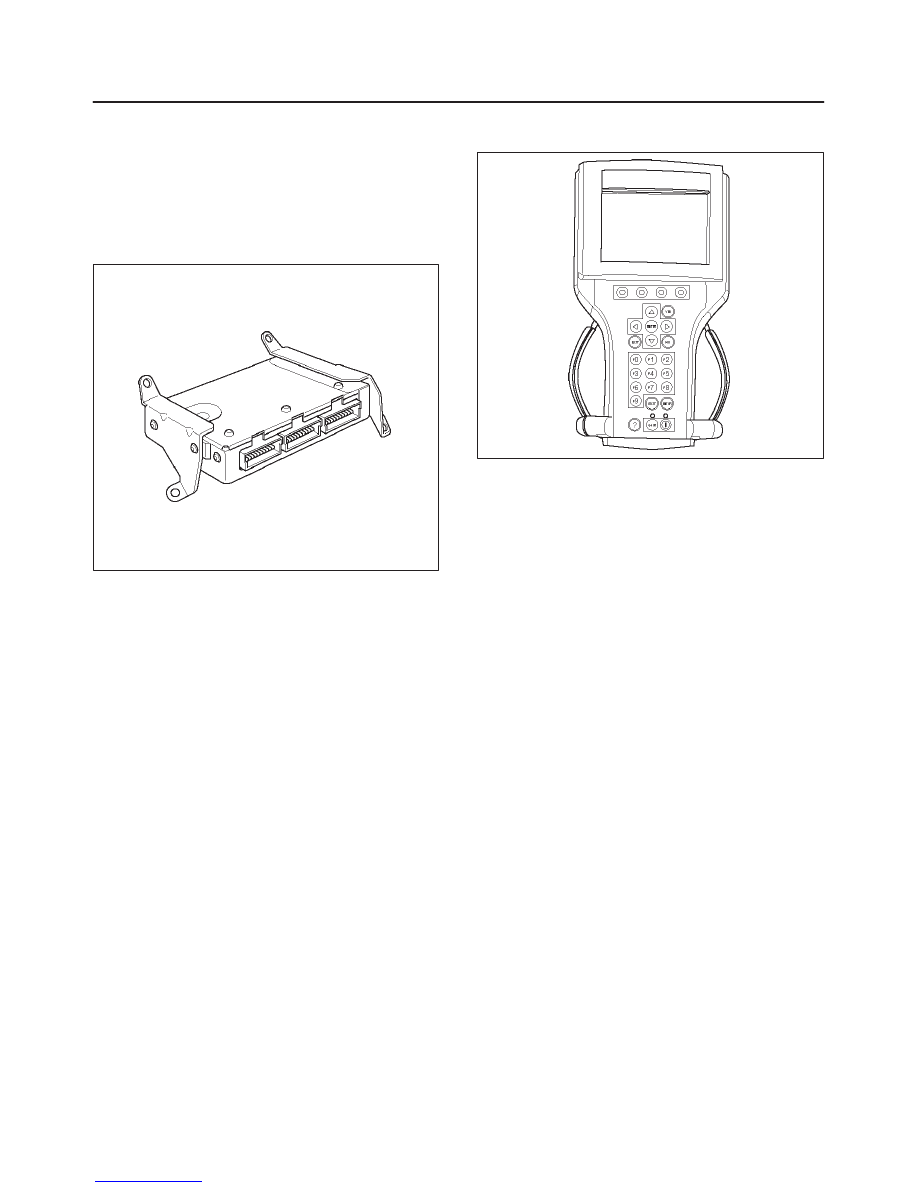
EEPROM
EEPROM
The Electronically Erasable Programmable Read Only
Memory (EEPROM) is a permanent memory that is
physically soldered within the PCM. The EEPROM
contains program and calibration information that the
PCM needs to control Powertrain operation.
014RX002
EEPROM Programming
1. Connect Tech 2 to the vehicle DLC and retrieve
information from the PCM. Ensure that the following
condition have been met:
f
Battery is fully charged.
f
The Ignition is in ON position.
f
Tech 2 cable is securely connected to DLC.
2. Download latest program and calibration from ITCS.
Always use latest ITCS software to program PCM.
Refer to Up–to–date ITCS user’s guide.
3. Reconnect Tech 2 to the DLC and program PCM.
f
Make sure the ignition is recycled after information
is retrieved.
f
Ensure the ignition is stay in ON position after
programming is started.
901RX031
Functional Check
1. Perform the On–Board Diagnostic System Check.
2. Start the engine and run for least one minute.
3. Check for DTCs using Tech 2.
4. If the PCM fails to program, proceed as follow:
f
Ensure that all PCM connections are OK.
f
Check the ITCS for latest version software.
f
Attempt to program PCM again. If PCM still cannot
be programmed properly, replace PCM. The
replacement PCM must be programmed.
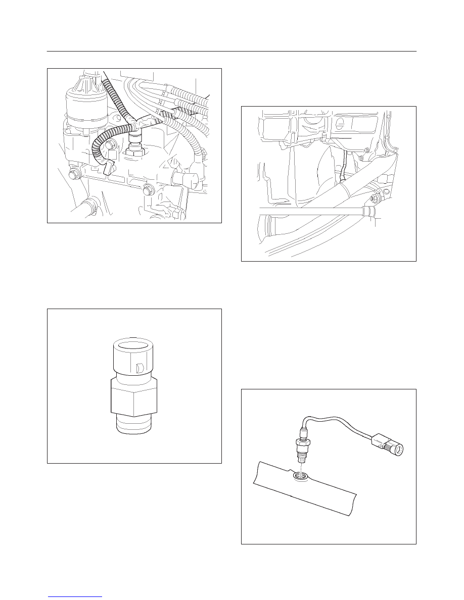
Engine Coolant Temperature
(ECT) Sensor
Removal Procedure
1. Disconnect the negative battery cable.
2. Drain enough engine coolant so that the coolant level
will be below the ECT sensor.
3. Remove electrical connector from the sensor located
on the intake manifold above the ignition coil.
6E1–385
RODEO X22SE 2.2L ENGINE DRIVEABILITY AND EMISSION
4. Unscrew the sensor from the manifold.
014RX008
Installation Procedure
1. Install the sensor into the intake manifold. Do not over
tighten.
2. Connect electrical connector.
3. Add engine coolant to required level. Refer to Engine
Cooling System Section.
4. Connect the negative battery cable.
0016
Heated Oxygen Sensor (HO2S)
Removal Procedure
1. Disconnect the negative battery cable.
2. Locate the two oxygen sensors.
f
Bank 1 sensor 1 is mounted on the exhaust pipe
ahead of the catalytic converter.
f
Bank 1 sensor 2 is mounted on the exhaust pipe
behind the catalytic converter.
3. Disconnect pig tail electrical connector.
IMPORTANT:
The pigtail is permanently attached to
the sensor. Be careful not to pull the wires out.
014RX010
4. Unscrew sensors form the exhaust pipe. Because of
the expansion and contraction of the metal in the
exhaust system over time, this may be difficult if the
engine temperature is below 48 degree C.
Inspection Procedure
NOTE: Both sensors are identical. Inspect each inthe
same way.
1. Inspect the pigtail and the electrical connector for
grease, dirt, corrosion and bare wire or worn
insulation.
2. Inspect the louvered end of the sensor for grease,
dirt, excessive carbon build up or other contaminants.
TS23739
6E1–386
RODEO X22SE 2.2L ENGINE DRIVEABILITY AND EMISSION
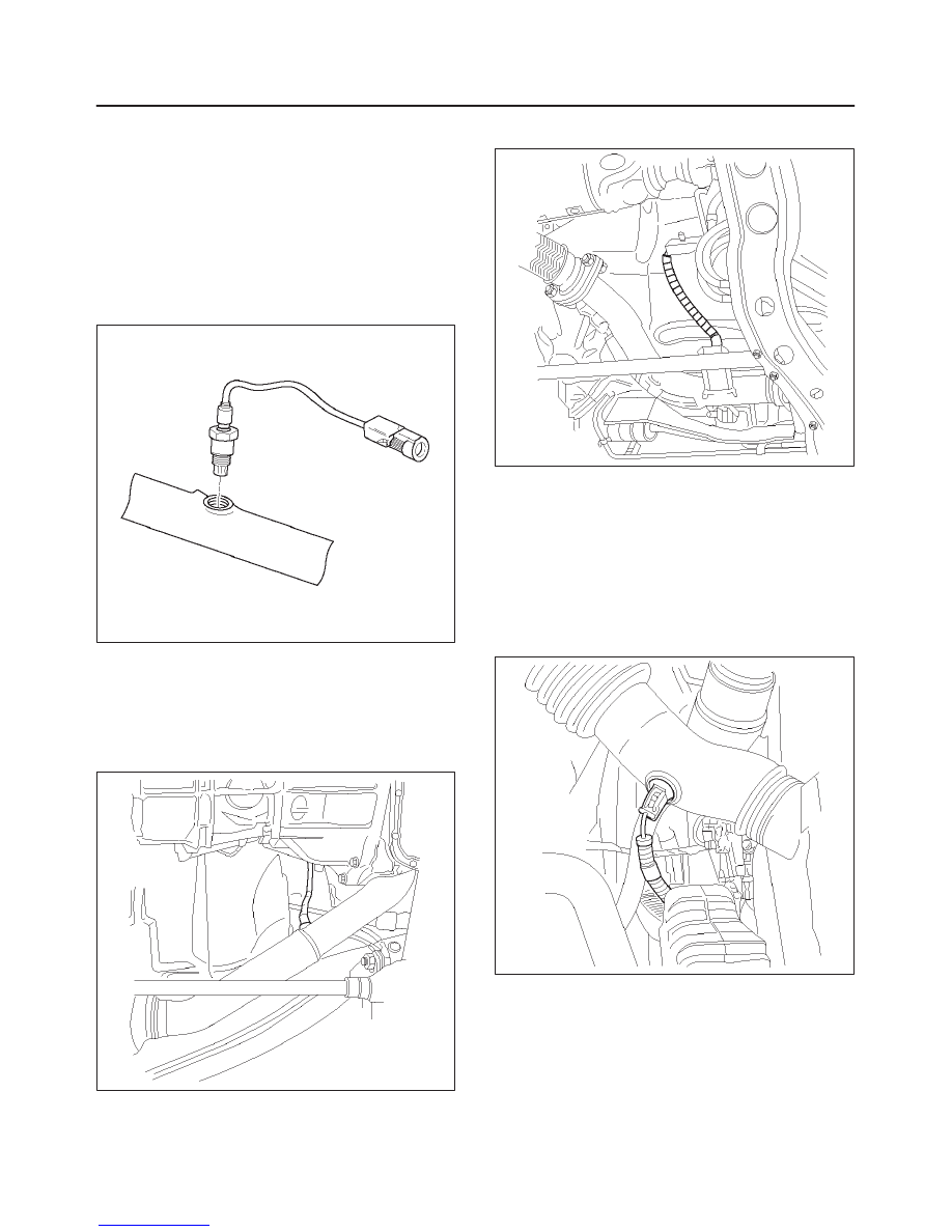
Installation Procedure
NOTE: If HO2S is reinstalled after removal, special
anti–seize compound or the equivalent should be applied
to the threads. Special anti–seize compound, (P/N
5613695), is used on the HO2S threads. This compound
consists of glass beads suspended in a liquid graphite
solution. The graphite burns away with exhaust heat, but
the glass beads will remain, making the sensor easier to
remove.
1. Apply anti–seize compound or the equivalent to the
thread.
TS23739
2. Install HO2S on the exhaust pipe.
3. Tighten the sensor to 55 Nm (40 lb ft)
4. Connect the pig tail to the wiring harness.
5. Connect the negative battery cable.
(Pre–Catalytic Converter Heater Oxygen Sensor Loca-
tion)
014RX010
(Post–Catalytic Converter Heater Oxygen Sensor
Location)
014RX009
Intake Air Temperature (IAT)
Sensor
Removal Procedure
1. Disconnect the negative battery cable.
2. The IAT sensor is located in the intake air duct
between the air filter and the throttle body.
014RX011
3. Disconnect the electrical connector from the sensor.
Нет комментариевНе стесняйтесь поделиться с нами вашим ценным мнением.
Текст